


4
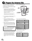
Before you begin, consider the following antenna
installation guidelines:
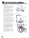
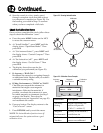
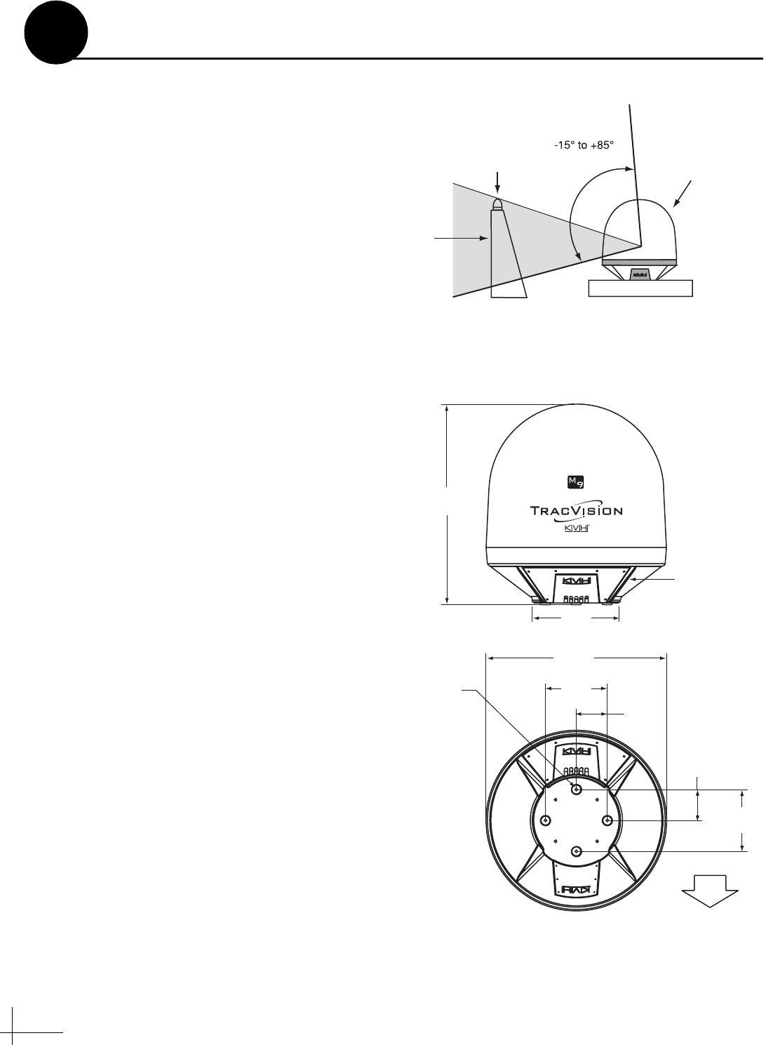
• Minimize blockage. The antenna requires a
clear view of the sky to receive satellite TV
(see Figure 3). The fewer obstructions, the
better the system will perform.
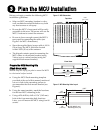
• Make sure the mounting surface is wide
enough to accommodate the antenna’s base
(see Figure 4). Also make sure it is flat, level,
strong enough to support the antenna’s
weight (85 lbs, 38.6 kg), and rigid enough to
withstand vibration.
• Be sure to preserve enough free space outside
the access hatch to allow a technician to
remove the hatch and perform maintenance.
• Select a location that is as close as possible to
the intersection of the vessel’s fore-and-aft
centerline and midships.
• Select a location that is not too high above the
waterline. Limit the height above the
waterline to less than 1/2 the vessel’s length.
• Do not mount the antenna at the same level
as the radar because the radar’s energy might
overload the antenna. Ideally, you should
mount the antenna 4 ft (1.2 m) above and 4 ft
(1.2 m) away from the radar.
• Select a location that is at least 4 ft (1.2 m)
away from any magnetized materials, large
ferrous masses, cranes, engines, derricks,
other antennas, devices with DC motors,
electric winches, high-amperage cables, or
battery banks. The antenna’s internal
compass sensor performs best in a benign
magnetic environment.
• If you are mounting the antenna on a steel
vessel, use an aluminum, brass, plastic, or
wood platform (NOT steel or iron) to position
the antenna at least 4 ft (1.2 m) above and 6 ft
(1.8 m) away from the steel surface.
Blocked!
Antenna
Vessel Platform
Mast
Look angle
Figure 3: Blockage from Obstruction
FWD
38.86"
(98.7 cm)
4x ø.50"
(4x ø13 mm)
ø35"
(ø88.9 cm)
12"
(30.5 cm)
6"
(15.2 cm)
6"
(15.2 cm)
12"
(30.5 cm)
Access Hatch
17"
(43.2 cm)
Figure 4: Antenna Dimensions
Side View
Bottom View
Plan the Antenna Installation
2