


6
Once you have identified a suitable antenna
mounting site, according to the guidelines
provided in Step 2, follow these steps to drill the
mounting holes and cable access hole to prepare
the site for installation.
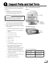
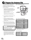
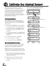
a. Unfold the antenna mounting template
(supplied in the Customer Welcome Kit) and
place it onto the mounting surface. Make sure
the “FWD” (forward) arrow points toward
the bow and is parallel to the vessel’s
centerline (see Figure 7).
NOTE: You don’t need to mount the antenna
exactly on the vessel’s centerline, but the
antenna’s forward arrow must be parallel to it.
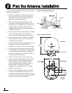
b. Use the template to mark the locations for the
four mounting holes on the mounting
surface.
c. Drill a 1/2" (13 mm) hole at the four
mounting hole locations you marked in
Step 4b. Later, you will insert four M10 bolts
from below to secure the antenna to the
mounting surface.
d. Mark a location for the cable access hole,
either in the center of the antenna mounting
hole pattern or in an area aft of the antenna.
Later, you will route the data/power and RF
cables through this hole and into the vessel.
e. Drill the cable access hole in the location you
marked in Step 4d. Be sure to size the hole
appropriately to accommodate the data/
power cable and all required RF cables (see
Figure 8 and Figure 9 to determine the
number and type of RF cables required).
Smooth the edges of the hole to protect the
cables.
Figure 7: Antenna Mounting Holes Layout
If you wish to route the cables through the
bottom of the antenna’s baseplate, rather than
connecting at the side, you will need to
modify the antenna’s baseplate. See
Appendix A on page 19 for details.
IMPORTANT!
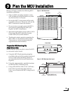
Figure 8: Number of RF Coax Cables Required
* Multiswitch required for 3 or more receivers.
** Multiswitch required for 5 or more receivers.
See Appendix B on page 23 for details.
Connecting to: # RF Cables
System with Dual LNB
1 receiver 1
2 or more receivers 2*
System with Quad LNB (Europe Only)
1 receiver 1
2 receivers 2
3 receivers 3
4 or more receivers 4**
Figure 9: RF Cable Guidelines
Cable Length Use Cable Type
≤ 75 ft (23 m) RG-6
> 75 ft (23 m) RG-11
Prepare the Antenna Site
4