


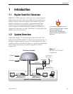
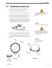
1.2.1 TracVision LF/SF Components
The antenna unit includes the antenna positioning mechanism,
signal front end, power supply and control elements. The
antenna is a parabolic dish mounting a dual-output low noise
block (LNB) converter with built-in preamplifier. A molded ABS
radome encloses the baseplate and is secured in place with
standard fasteners. Connectors on the back of the baseplate join
the power, signal, and control cabling from units inside the
vehicle.
1.2.2 Integrated Receiver/Decoder (IRD)
The IRD (purchased separately) receives satellite signals from the
antenna unit for signal decoding, processing, and channel
selection, and sends the signals to the TV set for viewing. In
addition, messages can be sent from the IRD to the antenna unit
and messages can be received from the antenna unit for display
on the television screen. The IRD also provides the interface for
the user to activate authorization for reception. Please refer to the
User’s Manual provided with your selected IRD for complete
operating instructions.
1.3 Materials Provided with
TracVision LF/SF
Table 1-1 lists the units, cables, and materials packed in the
TracVision LF/SF package by name and KVH part number.
Component KVH Part No.
Antenna Unit (TracVision LF) 01-0225-15
Antenna Unit (TracVision SF) 01-0225-14
RF Cable (28 ft)* 32-0417-28
Data/Power Cable (28 ft)* 32-0730-28
Kitpack** 72-0120
Installation and Operation Manual 54-0194
* RF and data/power cables may be supplied separately.
** A complete listing of kitpack contents is provided in Table 2-2.
1-2
A Guide to TracVision LF/SF
On-screen messages are not
available with a DISH Network IRD.
Table 1-1
TracVision LF/SF Packing List
Cables for the TracVision LF/SF are
stored beneath the antenna unit
during shipping.