2-7
Installation
54-0194 Rev. D
Installing Two IRDs and TVs
To connect a second TV and IRD to the TracVision LF/SF system,
you must connect a second RF cable to the antenna’s RF2
connector (see Figure 2-6). Route the other end of the RF cable
down into the vehicle and connect it directly to the second IRD.
Connecting Three or More IRDs and TVs
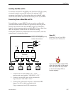
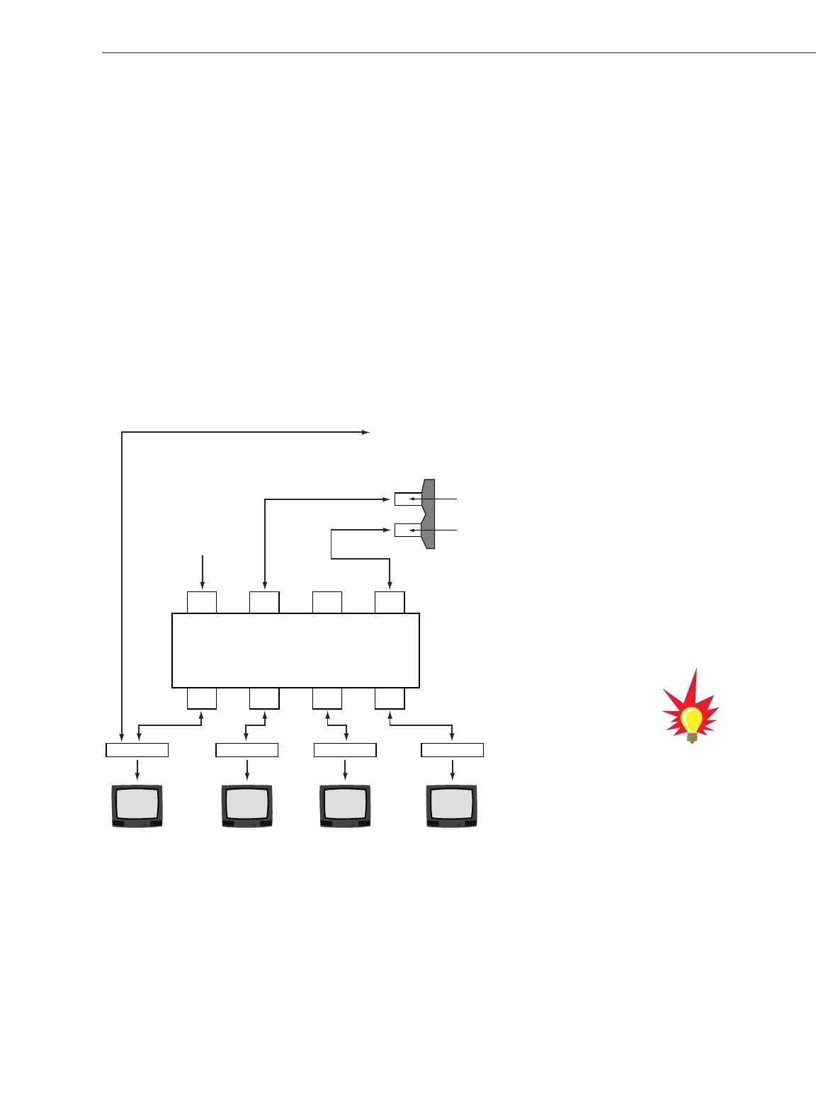
To install three or more IRD/TV pairs, an active multiswitch
(Channel Master model 6214IFD or equivalent) must be placed
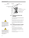
between the antenna unit and the IRDs. Figure 2-8 illustrates
typical wiring arrangements for multiple IRDs. If more than four
IRDs are required, contact KVH for additional wiring
instructions. Mount the multiswitch unit in accordance with the
manufacturer’s instruction sheet.
1. Connect the RF cable tagged “RF1” to the
multiswitch input labeled “LNB RHCP +13V.”
2. Connect a second RF cable to the multiswitch
input labeled “LNB LHCP +18V.”
3. Connect the multiswitch outputs to individual IRD
inputs. Use RG-6 cable terminated with
F-type connectors for all RF connections.
Multiswitch
DC In RHCP
+13V
VHF/UHF LHCP
+18V
Out 1 Out 2 Out 3 Out 4
DC Power
IRD #1 IRD #2 IRD #4IRD #3
TracVision RF Connectors
RF1
RF2
TracVision IRD Data Cable
Connector on Switchplate (Optional)
Figure 2-8
Installing Three or Four IRDs
Using an Active Multiswitch
If you are connecting multiple IRDs,
attach the data cable to the master
IRD. The master IRD must remain
on for the secondary IRDs to
function properly.


