2-9
Installation
54-0194 Rev. D
2.3.5 Connecting the Switchplate to
Vehicle Power
The switchplate must be connected to a +12 VDC, 2.5-3.5 amp
power supply to operate.
1. Disconnect vehicle power by removing the
appropriate vehicle fuse.
2. Run a cable from vehicle’s power (11-16 VDC) out
through the switchplate panel cutout.
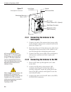
3. Connect the power cable to the switchplate’s
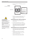
power terminals as shown in Figure 2-7.
2.3.6 Connecting the IRD Ground Wire
A grounding wire has been provided to connect your IRD to a
suitable ground and protect the system. Attach the grounding
wire to any suitable screw on the rear panel of the IRD with a
good contact with the IRD chassis. The other end should be
connected to a suitable ground, ideally the ground connector on
the switchplate (see Figure 2-7). Each IRD that you connect to
the TracVision system should have a similar ground
connection.
If you are using a multiswitch, you can ground the multiswitch instead
of the individual IRDs.
2.3.7 Installing the Switchplate
After completing the switchplate wiring, you need to install the
switchplate itself.
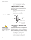
1. Carefully fit the switchplate assembly into the
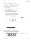
panel cutout (made in Step 2 of Section 2.3,
“Connecting System Components”) until the
switchplate is flush to the mounting surface.
2. Secure the switchplate to the mounting surface
using the two supplied #6 thread-forming screws.
3. Reinstall the vehicle fuse removed in Step 1 of
Section 2.3.5, “Connecting the Switchplate to Vehicle
Power.”
Before connecting the antenna unit
to vehicle power, remove the
appropriate vehicle fuse to prevent
a short circuit. Replace the fuse
after the connection to vehicle
power is complete.
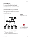
Be sure to connect a ground wire
from each IRD to a suitable ground,
ideally the switchplate’s ground
connector.


