


8
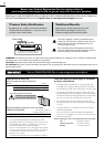
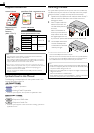
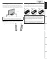
Supplied Accessorie
s
O
wner’s Manual
Q
uick Start Guide
Installation
EN
Installation
FR
Instalación
ES
If you have any questions, please visit our website at
www.
Best
Better
Good
magnavox.com/suppor
t
Quick
Start
R
egistration car
d
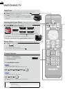
Remote Control
(
NF801UD)
B
atterie
s
(
AAA, 1.5V x 2)
AAA
AAA
TV
b
ase an
d
screw
s
Screws packed with this unit:
M
o
d
e
l
Quantity
y
Size
3
2MD311B
4
M4 x 20
3
2MD301B
26MD311B
26MD301B
22MD311B
3
M4 x 1
2
1
9MD311B
1
9MD301B
Note
•
I
f
y
ou lose the screws,
p
lease
p
urchase the above-mentioned
Philli
ps
h
ea
d
screws at your
l
oca
l
store
.
•
If you need to replace these accessories, please refer to the part
name and No. with the illustrations and call our toll free custome
r
support line found on the cover of this manual
.
When using a universal remote control to operate this unit.
•
M
a
k
e sure t
h
e component co
d
e on your un
i
versa
l
remote contro
l
i
s set to our brand. Refer to the manual accompanying you
r
remote control for more details
.
•
We do not guarantee 100% interoperability with all universal
remote contro
l
s
.
Symbols Used in this Manual
T
he following is the description for the symbols used in this
manual. Descri
p
tion refers to
:
T
V FUNCTIONS
AT SC
:
Di
g
i
ta
l
TV
operat
i
on
NTSC
: Analog / Cable TV operation
•
If neither symbol appears, the operation is applicable to both
.
DV
D
FU
NC
TI
ON
S
DVD
: Playback of DVD-video
CD
: Playback of audio C
D
•
If neither s
y
mbol a
pp
ears under the function headin
g
, o
p
eration is
app
li
ca
bl
e to
b
ot
h.
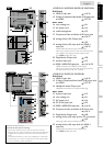
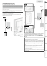
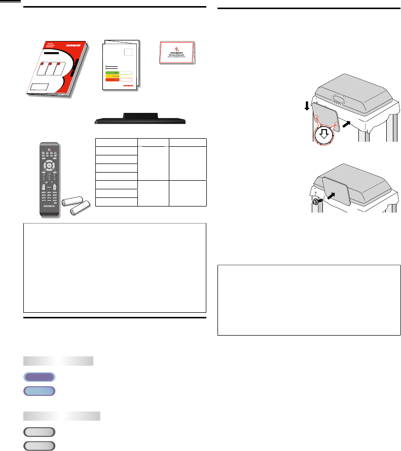
Attaching the Base
Y
ou must attac
h
t
h
e
b
ase to t
h
e un
i
t to
h
ave
i
t as a ta
bl
e top
u
nit. Be sure the front and rear of the base match the proper
d
irection. At least 2
p
eo
p
le are re
q
uired for these ste
p
s
.
1
Spread a thick and soft cloth over a table as shown at step 2
.
P
lace the main unit face down onto it. Make sure not to
d
amage t
h
e screen
.
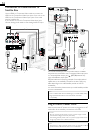
2
Insert 2 hooks under the
b
ottom of the main unit
i
nto base holes
(
shown b
y
arrow
➀
), then move the
➀
b
ase
i
n t
h
e
di
rect
i
on as
s
h
own
by
arrow
➁
unt
il
i
t
sto
p
s an
d
t
h
e screw
h
o
l
es
are a
lig
ne
d
.
M
a
k
e sure not
FRONT
➁
➀
t
o put the AC power cord between the base and the unit
.
3
D
r
i
ve
Philli
ps
h
ea
d
screws
i
nto t
h
e t
h
rea
d
e
d
h
o
l
es
at the bottom of the base
unt
il
t
h
ey are t
i
g
h
t
.
To remove the base from this unit
•
U
nscrew t
h
e
Phillip
s
h
ea
d
screws
i
n ste
p
3
.
A
fter the screws are removed, move the base in the o
pp
osite direction
as s
h
own
by
arrow
i
n ste
p
2
, then
p
ull the base u
p
toward the rear of
t
he unit. Be careful not to dro
p
the base when
y
ou remove it
.
Note
•
W
hen attaching the base, ensure that all screws are tightly fastened. If
t
he base is not properly attached, it could cause the unit to fall, resulting
i
n
i
n
j
ur
i
es as we
ll
as
d
amage to t
h
e un
i
t
.
•
Make sure to use a table which can support the weight of this unit and
i
s
l
arger t
h
an t
hi
s un
i
t
.
•
M
a
k
e sure t
h
e ta
bl
e
i
s
i
n a sta
bl
e
l
ocat
i
on
.
•
W
hen attaching the base, ensure that FRONT
↑
wr
i
tten on t
h
e
b
ase
i
s
u
pward. If it’s not upward, the 2 hooks don’t fi t in the base
.