


18
Connections
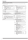
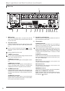
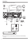
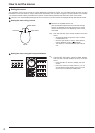
Connecting to CCTV camera, monitor, and sensor
To OUTPUT A VIDEO or
OUTPUT A S(Y/C) connector
One of either codes
should be connected.
To VIDEO IN or
S(Y/C) IN connector
To VIDEO IN
connector
To OUTPUT B
connector
To CAMERA IN 1 connector
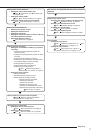
Up to 16 cameras
T
o GND
terminal
To ALARM IN terminal
corresponding to the
camera #.
To LAN
DX-ZD5UE(Z)
Up to 7 units can be mounted
at the same time.
To SERIAL
BUS
RS232C type
dome camera
(camera controller)
RS422 type
dome camera
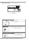
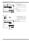
Processing the connecting line
Connection on the ALARM IN terminals, the I/O terminals, and RS485/RS422
Compatible power lines ø0.32 - ø0.65 mm (AWG 28 - 22)
Cut the designated area from the electric wire’s outer covering
(vinyl portion).
5-7mm
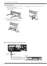
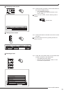
Clamp the USB cable using the supplied
cable clamping band in order to prevent the
accidental removal of the cable.
( See page 20.)
Clamp the power cord using the supplied
cable clamping band in order to prevent the
accidental removal of the cable.
( See page 20.)
Dome camera
Camera #1
Monitor
Monitor
Sensor #1
PC
PC
Mouse
Power code
External recording device
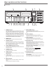
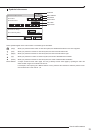
PTZ control connectors
You can connect various devices to control this unit from them, or to control them from this unit. However, depending on
the operational condition of this unit, the operational speed of this unit may become slower or control of the external device
may be delayed.