


19
Connections
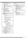
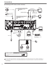
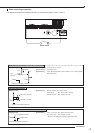
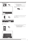
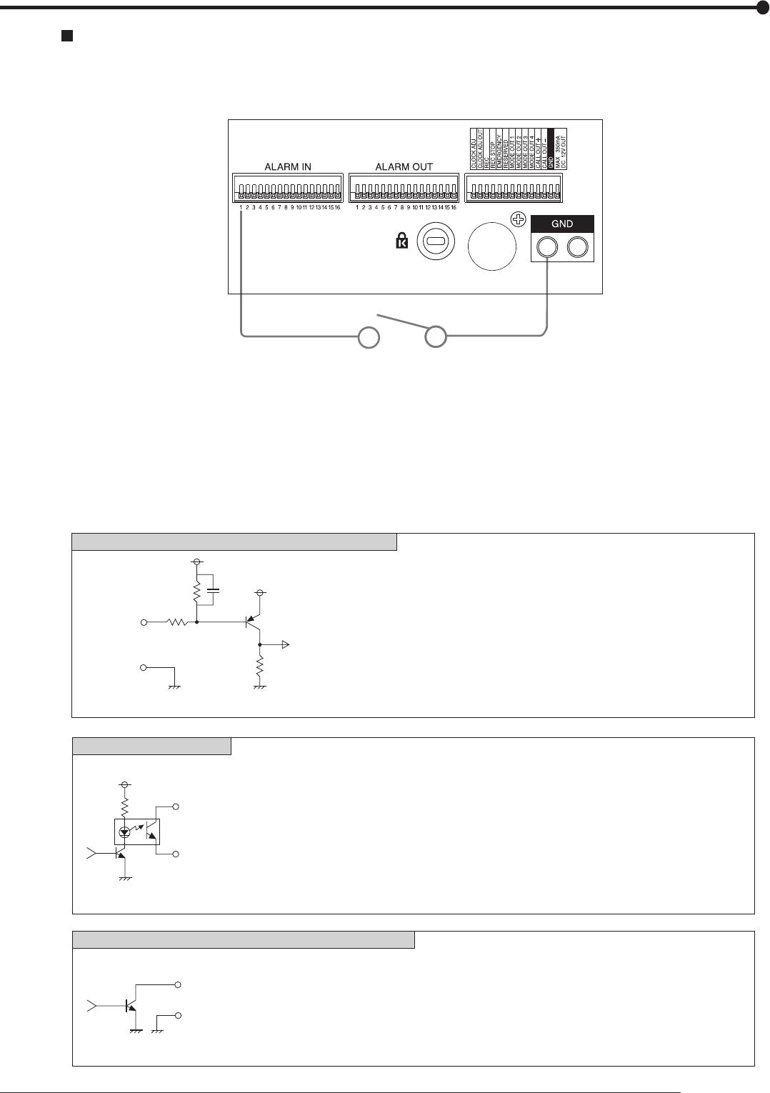
Alarm recording connection
The diagram below shows an example connection for setting alarm signal to sensor number 1.
Alarm switch
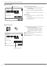
[Input condition]
[Input interval]
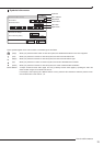
[Specification]
[Specification]
[Specification]
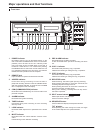
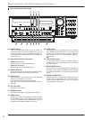
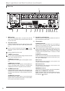
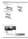
CALL OUT output terminal
ALARM OUT/MODE OUT 1 to 4/CLOCK ADJ output terminals
EMERGENCY/ALARM IN/REC/CLOCK ADJ input terminals
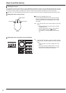
[Output Circuit]
[Input Circuit]
[Output Circuit]
ground of 200 ms or more
1 second or more
Active: When terminals are short-circuited or “Low” Level is applied.
Non active: Open.
Warning signal (Photo coupler output)
Active: Short Max. Drive current 7 mA DC.
Non active: Open. Max. Voltage +24 V DC.
Active: “Low” Level Max. Drive current 30 mA DC.
Non active: Open. Max. Voltage +24 V DC.
* Be sure to use these terminals within above rated value.
<Interface circuit inside of the unit>
5V
5V
10kΩ
22kΩ
Input
terminal
0.047µF
GND
4.7kΩ
<Interface circuit inside of the unit>
CALL OUT + terminal
CALL OUT - terminal
<Interface circuit inside of the unit>
Output terminal
GND terminal