


Chapter 2. Connecting 27
COMPONENT
YPbPr (480i/480p/720p/1080i)
INPUT
1
2
S-VIDEO
VIDEO
AUDIO-
LEFT/
(MONO)
AUDIO-
RIGHT
DTV/CABLE/
VHF/UHF
ANT 1 / MAIN
ANT 2 / AUX
DIGITAL
AUDIO
OUTPUT
CableCARD™ USE WITH ANT 1 CARD TOP
1
2
Y
Pb
Pr
AUDIO-
LEFT/
(MONO)
AUDIO-
RIGHT
OUTPUT
AUDIO
OUTPUT
RECORD
OUTPUT
DVI
Analog Audio
1 2
VIDEO
AUDIO-
LEFT/
(MONO)
AUDIO-
RIGHT
MONITORLINK™/HDMI
VIDEO 480i/480p/720p/1080i
AUDIO PCM LINEAR
1
2
IEEE 1394
INPUT/
OUTPUT
Net Command
IR EMITTER
¸
',INK
¸
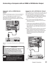
INPUT
PC - 60Hz
VGA, W-VGA,
SVGA, W-SVGA,
XGA, 1280 X 720
)46
$BCMF#PY
CBDLQBOFMTFDUJPO
*/
065
065
5808":41-*55&3
*/
065
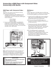
*ODPNJOH
$BCMF
3'4QMJUUFS
7$3CBDLQBOFM
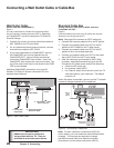
*GZPVS7$3IBTB
WJEFPDIBOOFMPS3'
0/0''TXJUDITFUJU
UP0''
"UUBDIPOMZPOFWJEFP
DBCMFUZQFTUFQ
4WJEFPSFDPNNFOEFE
JGBWBJMBCMF
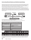
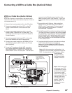
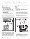
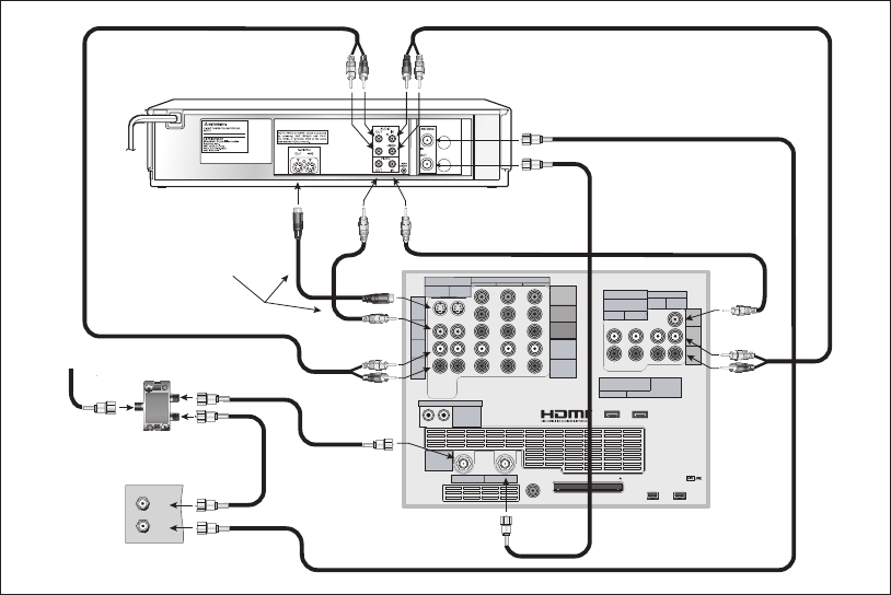
VCR to a Cable Box (Audio & Video)
Figure 6
A two-way RF splitter, 4 coaxial cables, right and left audio
cables and an S-Video or Video cable are required. These are
not included with the TV.
1. Connect the incoming cable to IN on the RF splitter.
2. Connect one coaxial cable from OUT on the RF
splitter to ANTENNA IN on the cable box back
panel.
3. Connect one coaxial cable from OUT on the RF
splitter to ANT-1 MAIN on the TV back panel. This
connection also allows you to use the TV Guide On
Screen® feature.
4. Connect one coaxial cable from OUT on the cable
box to ANTENNA IN on the VCR back panel.
5. Connect one coaxial cable from ANTENNA OUT on
the VCR back panel to ANT-2 AUX on the TV back
panel (optional).
6. To use the TV speakers with the VCR, connect a
set of audio cables from AUDIO OUT on the VCR
back panel to INPUT-1 AUDIO-LEFT (MONO) and
AUDIO-RIGHT on the TV back panel. The red cable
Figure 6. Connecting a VCR to a Cable Box
Note: NetCommand®
will assume your VCR
is connected to inputs
as shown on this page.
If you use any other
inputs for your VCR or
add a second VCR, this
change must match
in the NetCommand
system. See Edit
NetCommand... in
Chapter 3 for more
information.
Connecting a VCR to a Cable Box (Audio & Video)
connects to the R (right) channel and the white
cable connects to the L (left) channel. If your VCR
is mono (non-stereo), connect only the white (left)
cable.
7. Connect either an S-Video or Video cable from
VIDEO OUT on the VCR back panel to INPUT 1
VIDEO on the TV back panel. Only one type of
video cable should be connected. S-Video is
recommended, if available.
8. For NetCommand® controlled recordings (including
TV Guide On Screen), connect a set of audio cables
from AUDIO IN on the VCR back panel to RECORD
OUTPUT/AUDIO-LEFT (MONO) and AUDIO-RIGHT
on the TV back panel. The red cable connects to
the R (right) channel and the white cable connects
to the L (left) channel.
9. Complete the NetCommand controlled recordings
and TV Guide On Screen connections by
connecting a Video cable from VIDEO IN on the
VCR back panel to RECORD OUTPUT/VIDEO on
the TV back panel.
Note: With this connection configuration, it is
possible to view live cable programs through the
VCR. For best picture quality, however, always
view live cable
programs directly
from the cable box
instead of the VCR.