


32 Chapter 2. Connecting
Connecting the IR Emitter NetCommand
®
If a single emitter end can be placed in a
position that will operate more than one device,
do not use a separate emitter end for the
additional device. A single device receiving
remote control signals from too many emitters
or remote controls may not respond at all.
IMPORTANT
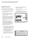
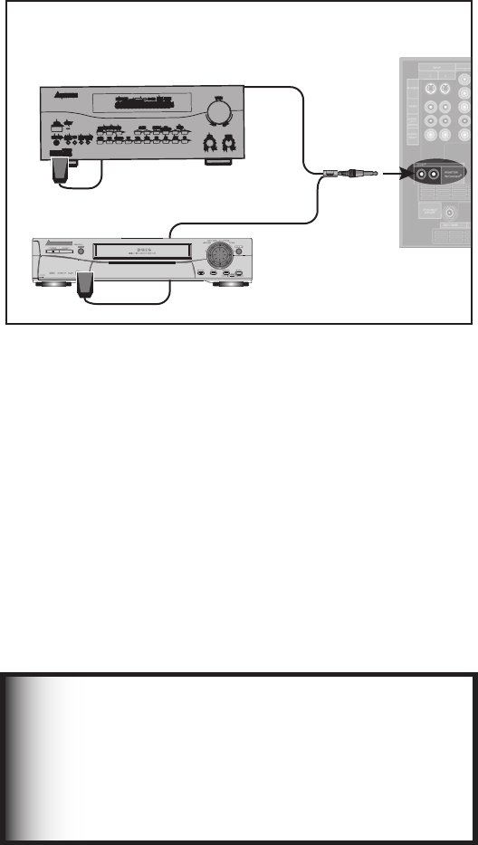
IR Emitter NetCommand®
Figure 15
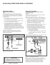
An IR emitter cable is included with the TV.
The emitters connected to these jacks are used by the
NetCommand system to control other devices such as
VCRs, DVD players, Cable boxes and Satellite receivers.
1. Connect the plug end of the supplied IR Emitter
Cable to either one of the IR Output NetCommand
jacks on the TV back panel.
2. Run the cable for each of the emitter ends under,
along side or over the top of each device to be
controlled to the area of the front where the remote
control sensor is located.
3. Place the emitter end in front of the remote control
sensor of the device to be controlled. The emitter
bulb should face the remote control sensor. This
bulb emits infrared light in a cone shaped pattern.
The bulb needs to be placed far enough from the
remote control sensor to allow the cone pattern to
include the sensor.
The remote control sensor is usually behind the
plastic window of the front display panel. It is
sometimes visible when you look through the
display plastic using a flashlight and is normally a
round or square cutout behind the plastic. If you
cannot see the sensor and the device’s Owner’s
Guide does not specify the location, you can find it
by using the device’s remote control.
a. Hold the remote about 1/2 inch from the front of
the device. Starting from one end of the display
window plastic, press the POWER button.
b. If the device does not respond, move the remote
control 1 inch toward the center and try again.
c. Repeat this until the device responds.
d. Note this location and then start over from the
other end of the display window plastic, repeating
until the device responds again.
The remote control sensor will be somewhere
between these two positions. This is usually
enough accuracy for the placement of the IR
emitters.
• With some devices, the emitter works better facing
downward from the top of the device. Some
experimentation may be needed.
• The emitter end being used can be secured in place
using double stick tape.
• If you are not going to
be using all emitter ends, place
the unused ends behind the devices so that they
cannot send signals to the remote control sensors.
% *( *5" -
46330 6/%
4
$)
57CBDL
QBOFMEFUBJM
0UIFS"7EFWJDF
"7SFDFJWFS
Figure 15. Connecting IR Emitter NetCommand