6 WIRING
6.2 Wiring Procedure
33
6
6.2 Wiring Procedure
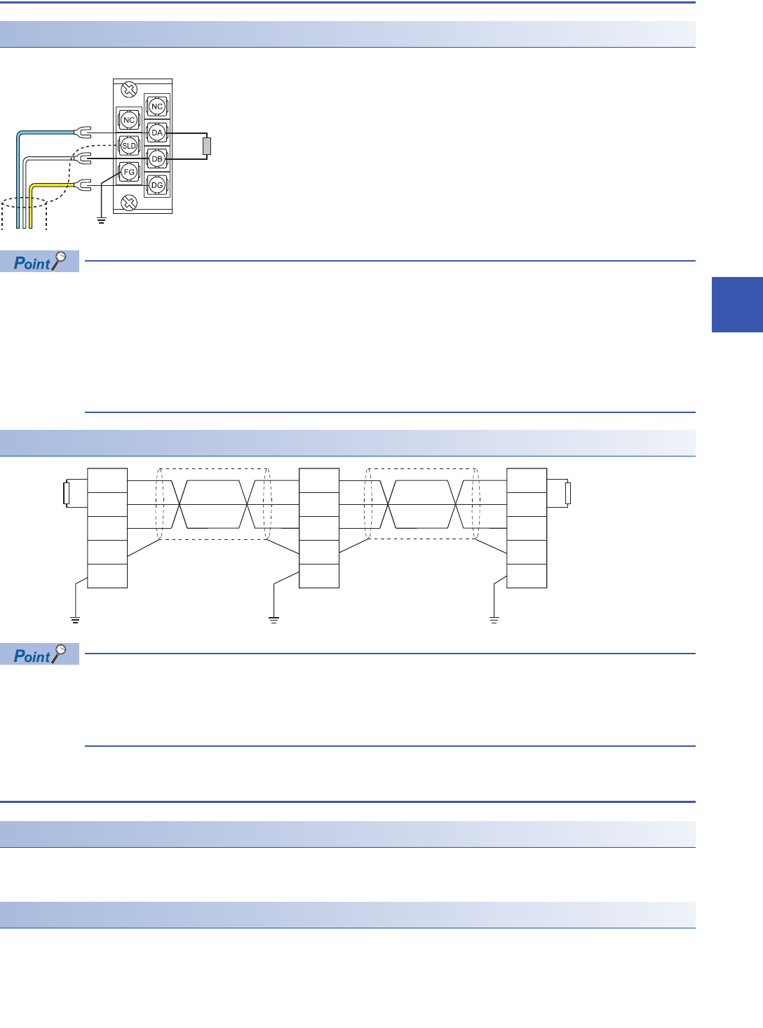
Wiring to terminal block
Shows wiring to the terminal block.
• Connect the terminating resistors between the DA and DB terminals.
• Connect the shield wires of a Ver.1.10 compatible CC-Link dedicated cable to the SLD terminal through the
FG terminal. Then ground the cables at both ends with a ground resistance of 100 ohms or less. The SLD
and FG terminals are connected inside.
• For the terminal processing of when connecting the Ver.1.10-compatible CC-Link dedicated cable to the
terminal block, do not unfasten the DA/DB/DG cable (three wires in one cable) or remove the sheath more
than necessary. (For cables with fillers, cut them using a tool.)
Wiring example
• No restrictions apply to the connection order of a master/local module. (The cables need not be connected
in the order of station number.)
• The star topology cannot be used. Note, however, that the T-branch connection can be used. ( Page 34
T-branch Connection)
6.3 Product for Wiring
Cables that can be used
Use Ver.1.10 compatible CC-Link dedicated cables.
Note, the cables need not be connected in the order of station number.
Terminating resistor to be used
Connect the terminating resistors included with the modules at both ends of the modules in the CC-Link system.
Terminating
resistor
(Blue)
(White)
(Yellow)
DA
DB
DG
SLD
FG
DA
DB
FG
SLD
DA
DB
FG
SLD
DG DG
Terminating
resistor
Ver.1.10-compatible
CC-Link dedicated cable
(Blue)
(White)
(Yellow)
Ver.1.10-compatible
CC-Link dedicated cable
Terminating
resistor
(Blue)
(White)
(Yellow)
(Blue)
(White)
(Yellow)
(Blue)
(White)
(Yellow)


