


9
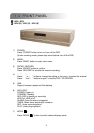
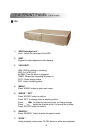
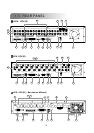
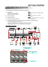
1) DISK ARRAY PORT:
Connect to disk array for extend HDD capacity.
2) IR:
Connect to IR receiver.
3) RS485:
Connect to external device (such as PTZ camera) with RS485-A and RS485-B.
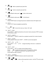
4) EXTERNAL I/O PORT:
Connect to external device. Control external device or get controlled remotely by
external device (alarm input, external alarm, PTZ camera).
5) USB PORT:
Support firmware update and files backup.
6) D/V PORT (Digital Video Port):
Connect to VGA connector card.
7) LAN:
Connect to Internet by LAN cable.
8) LINK / ACT LED light:
When the Internet is activated, the LED light will be on.
9) CALL MONITOR:
Connect to CALL monitor. Show the channel switch display. When the alarm is
triggered, the call monitor will show the image of the triggered channel for a period of
time.
10) POWER:
Connect to provided adapter.
11) FAN:
For ventilation.
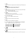
12) VIDEO INPUT (CHANNEL 1 – 16 / CHANNEL 1 – 8 / CHANNEL 1 – 4) :
Connect to video source, such as camera.
13) LOOP (CHANNEL 1 – 16 / CHANNEL 1 – 8 / CHANNEL 1 – 4) :
Video output.
14) 75 / HI:
When using Loop function, please switch to HI. When you don’t use Loop function,
please switch to 75 .
15) MONITOR:
Connect to Main monitor.
16) AUDIO IN (1-4):
Connect to audio source, such as camera which equipped with audio function.
When users start the recording function, the audio input will be recorded .
17) AUDIO OUT :
Connect to monitor or speaker.
With 2 mono audio outputs from the same source.
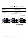
1234
2: RS485B
3: RS485A