


APPENDIX #2
APPENDIX #2
APPENDIX #2
APPENDIX #2
–
–
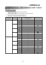
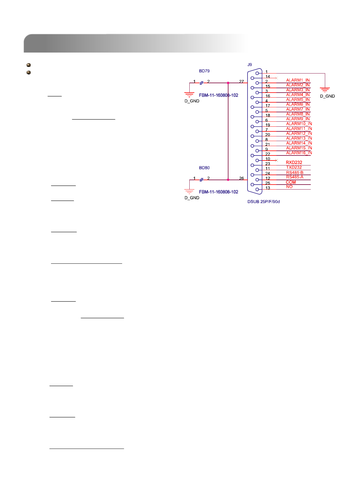
PIN CONFIGURATION
PIN CONFIGURATION
51
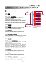
PIN 1.
GND
GND
GROUND
PIN 2. ~ PIN 9.
ALARM INPUT
ALARM INPUT
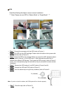
To connect wire from ALARM INPUT ( PIN 2 -- 9 ) to
GND ( PIN 1 ) connector,
DMR will start recording and buzzer will be on.
When Menu/ Camera/ Alarm is set up to “Low” : When alarm
input signal is “ Low ”, the unit starts to record and buzzer.
When Menu/ Camera/ Alarm is set up to “High” : When alarm
input signal is “ High ”, the unit starts to record and buzzer.
PIN 10.
PIN OFF
PIN OFF
PIN 11.
TXD232
TXD232
DVR can be controlled remotely by the keyboard of PC,
using RS-232 serial communications signals.
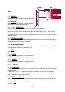
PIN 12.
RS485
RS485
-
-
A
A
DVR can be controlled remotely by the keyboard of PC,
using RS-485 serial communications signals.
PIN 13.
EXTERNAL ALARM NO.
EXTERNAL ALARM NO.
Under normal operation COM disconnect with NO. But when
Alarm triggered, COM connect with NO.
Attention: Voltage restrictions is under AV/DC 30V.
PIN 14.
PIN OFF
PIN OFF
PIN 15. ~ PIN 22.
ALARM INPUT
ALARM INPUT
To connect wire from ALARM INPUT ( PIN 15 -- 22 ) to GND
( PIN 1 ) connector,
DMR will start recording and buzzer will be on.
When Menu/ Camera/ Alarm is set up to “Low” : When alarm
input signal is “ Low ”, the unit starts to record and buzzer.
When Menu/ Camera/ Alarm is set up to “High” : When alarm
input signal is “ High ”, the unit starts to record and buzzer.
PIN 23.
RXD232
RXD232
DVR can be controlled remotely by the keyboard of PC,
using RS-232 serial communications signals.
PIN 24.
RS485
RS485
-
-
B
B
DVR can be controlled remotely by the keyboard of PC,
using RS-485 serial communications signals.
PIN 25.
EXTERNAL ALARM COM
EXTERNAL ALARM COM
Under normal operation COM disconnect with NO. But when
alarm triggered, COM connect with NO.
Attention: Voltage restrictions is under AV/DC 30V.
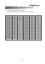
16CH / 8CH
16CH (D) / 8CH (D) / 4CH (D)