


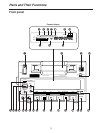
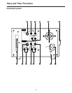
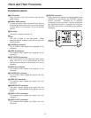
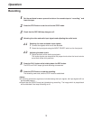

9
RS-
232C
AC IN
SIGNAL
GND
OUTPUT
CH1
CH2
AUDIO 2
CH1
CH2
AUDIO 1
VIDEO
MONIT
VIDEO
S-VIDEO
INPUT
CH1
CH2
AUDIO
REF
VIDEO
VIDEO
S-VIDEO
Connector panel
1
AC IN socket
Plug one end of the unit’s power cord into this
power socket.
2
SIGNAL GND terminal
In order to reduce noise, connect this terminal to
the signal grounding terminal on one of the devices
to which the unit is connected. This is not a safety
ground.
3
Fan motor
This motor is used to cool the unit.
4
Grip
This grip is fitted on the side panel. When
operating the unit, however, place the unit flat on its
bottom surface.
5
S-VIDEO IN connector
The S-VIDEO video signals are supplied to this
connector.
6
VIDEO IN connector
The analog video signals are supplied to this
connector.
7
REF VIDEO IN connector
This is connected to the reference video signal
when the unit is to be synchronized with the
reference sync signals of an external unit during
playback.
8
AUDIO IN connectors
The analog audio signals are supplied to this
connector.
9
S-VIDEO OUT connector
The S-VIDEO video signals are output from this
connector.
:
VIDEO OUT connector
The analog video signals are output from this
connector.
;
MONITOR OUT connector
The video monitor signals are output from this
connector. Superimposed video signals can be
output.
<
AUDIO 1 OUT connectors
The analog audio signals are output from this
connector.
=
AUDIO 2 OUT connectors
The analog audio signals are output from this
connector.
>
RS-232C connector
Editing operations can be conducted speedily and
efficiently by connecting the RS-232C remote
control (AJ-A250 - available as an optional
accessory) to this connector. Various operations
can be performed from a computer by using the
RS-232C cable which is available as an optional
accessory.
RS-232C
connector
Parts and Their Functions