


– 47 –
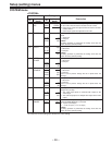
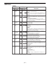
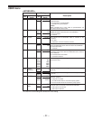
USER menu
<BASIC>
Item Setting
No.
Superimposed
No.
Superimposed
Description
display display
000 P-ROLL 0000 0S
..
..
TIME . .
0005 5S
..
..
..
0015 15S
001 LOCAL 0000 DIS
ENA
0001 ST&EJ
0002 ENA
002 TAPE 0000 ±12h
TIMER 0001 24h
003 REMAIN 0000 OFF
SEL 0001 ON
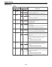
004 SETUP 0000 OFF
NUMBER 0001 ON
005 METER 0000 CUE
SEL 0001 VIDEO
006 SYNCHRO- 0000 OFF
NIZE 0001 ON
007 SUPER 0000 OFF
0001 ON
008 DISPLAY 0000 TIME
SEL
0001 T&STA
0002 T&S&M
The underline on the setting item denotes the initial setting.
This sets the preroll time which can be set from 0 to 15
seconds in 1-second increments.
<Note>
When the unit is set to automatic editing [PREVIEW, AUTO
EDIT], the unit will not operate if the preroll time is set to 0
seconds.
This selects the buttons which can be operated on the front
panel when the REMOTE/LOCAL switch has been set to
REMOTE.
0: No buttons can be operated.
1: Only the STOP and EJECT buttons can be operated.
2: All buttons except for the RECORDER and PLAYER
buttons can be operated.
This selects the 12 or 24 hour display for the CTL counter.
0: 12 hour display
1: 24 hour display
This selects whether the remaining tape time is shown on the
front panel.
0: Not shown.
1: Shown.
<Note>
Even when “Shown” is selected, the remaining tape time is not
shown while the unit is calculating the remaining tape time
after ejecting or inserting the cassette.
This selects whether the SETUP-MENU No. is displayed on-
screen.
0: The SETUP-MENU No. is not displayed.
1: The SETUP-MENU No. is displayed.
This selects whether the level meters are to display the CUE
track signal level or the video signal level.
0: The CUE track signal levels are displayed.
1: The video signal levels are displayed.
This selects whether or not to synchronize between two VTRs.
0: No synchronization. The editing points deviate several
frames, but editing can be started quickly.
1: Synchronization. Allows for error-free editing.
This selects whether the time code and other super display
which are output to the VIDEO OUT 3/SERIAL OUT 3 con-
nector is to shown.
0: Not shown.
1: Shown.
This selects what information is to be provided by the time code
and other super displays output to the VIDEO OUT 3/SERIAL
OUT 3 connector.
0: Time only.
1: Time and status.
2: Time, status and mode.
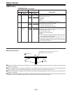
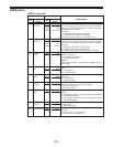
<Note>
•
An error message is displayed when an warning or error
occurs.