


L
R
PC IN
AUDIO IN
PC
AV IN
MONITOR
OUT
AV1 IN
COMPONENT
VIDEO
COMPONENT
S VIDEO
MONO MONO MONO
VIDEO
Y
L
R
AUDIO
Y
P
B
/C
B
P
R
/C
R
P
B
/C
B
P
R
/C
R
L
R
AUDIO
AV2 IN AV4 IN
L
R
AUDIO
IN
12
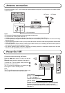
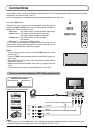
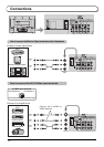
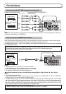
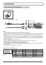
Connections
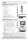
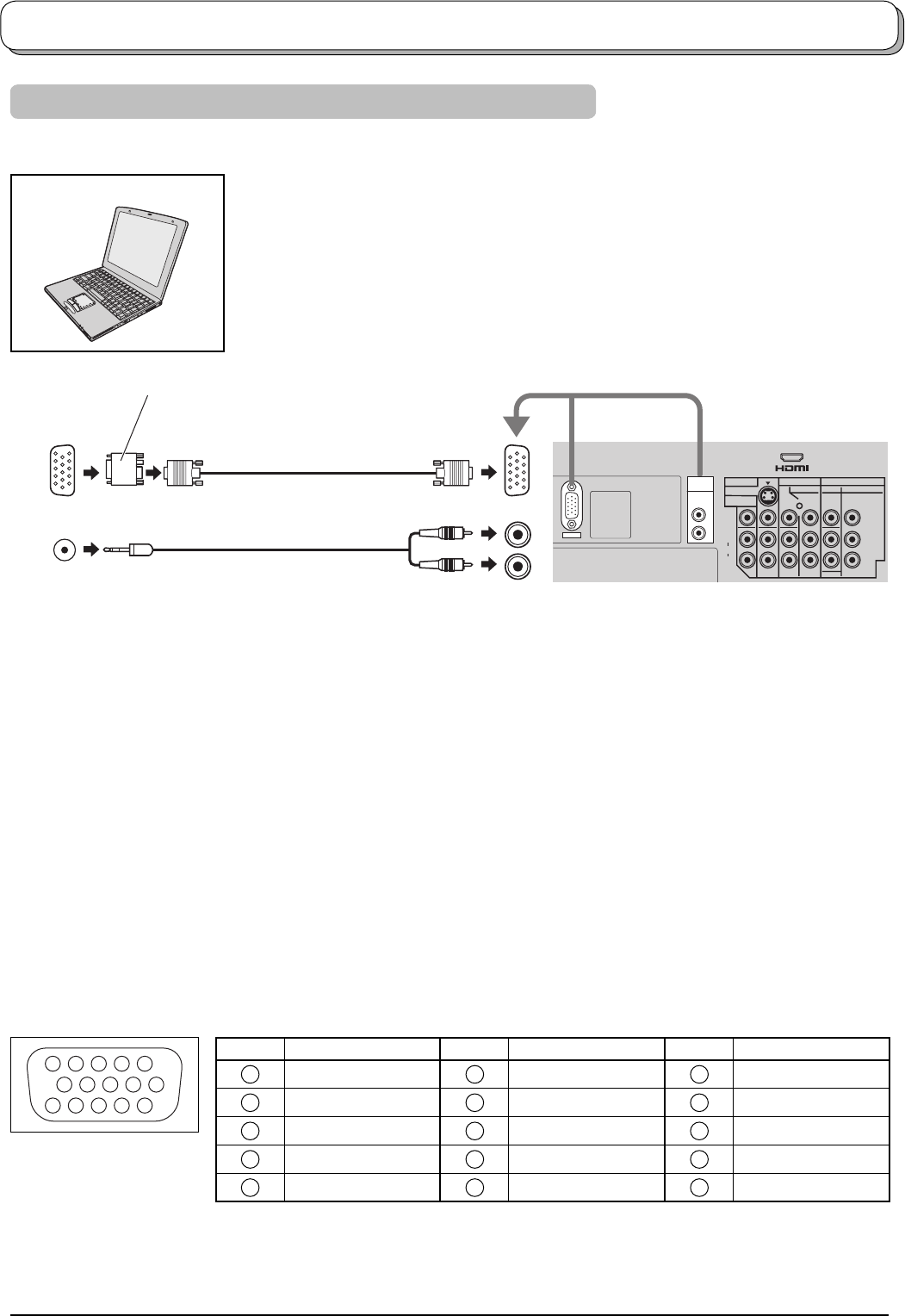
How to connect the PC Input terminal
Notes:
• Connect a cable which matches the audio output terminal on the computer.
• Computer signals which can be input are those with a horizontal scanning frequency of 31 to 69 kHz and vertical
scanning frequency of 59 to 86 Hz. (However, the image will not be displayed properly if the signals exceed 1,024
lines.)
• The display resolution is a maximum of 768 × 768 dots (TH-42PV500A), 1,024 × 768 dots (TH-50PV500A) when
the aspect mode is set to “4:3”, and 1,024 × 768 dots (TH-42PV500A), 1,366 × 768 dots (TH-50PV500A) when the
aspect mode is set to “16:9”. If the display resolution exceeds these maximums, it may not be possible to show fi ne
detail with suffi cient clarity.
• Some PC models cannot be connected to the set.
• There is no need to use an adapter for computers with DOS/V compatible D-sub 15P terminal.
• The computer shown in the illustration is for example purposes only.
• Additional equipment and cables shown are not supplied with this set.
• Do not set the horizontal and vertical scanning frequencies for PC signals which are above or below the specifi ed
frequency range.
• For applicable PC signals information see page 41.
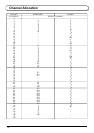
Signal Names for D-sub 15P Connector
1
678
3
9
45
10
15 14 13 12 11
2
Pin Layout for PC Input
Terminal
Pin No. Signal Name Pin No. Signal Name Pin No. Signal Name
1
R
6
GND (Ground)
11
NC (not connected)
2
G
7
GND (Ground)
12
NC (not connected)
3
B
8
GND (Ground)
13
HD/SYNC
4
NC (not connected)
9
NC (not connected)
14
VD
5
GND (Ground)
10
GND (Ground)
15
NC (not connected)
COMPUTER
RGB
AUDIO
(D-sub 15p)
(Stereo plug)
Conversion adapter (if necessary)
Example of input signal source