


C2629M-E (7/09) 21
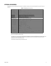
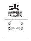
Back Panel Layout
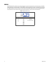
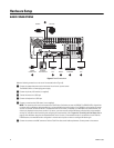
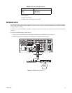
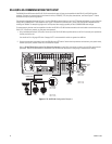
IMPORTANT NOTE. PLEASE READ.
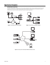
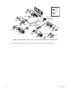
The network implementations in this document are shown as general representations only and are not intended to show detailed network
topologies. Your actual network will differ, requiring changes or perhaps additional network equipment to accommodate the systems as
illustrated. Please contact your local Pelco representative to discuss your specific requirements.
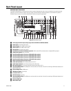
Figure 8. Back Panel Layout
ì Autoranging AC Power Input (voltage range between 100 VAC and 240 VAC, 50/60 Hz)
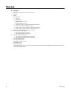
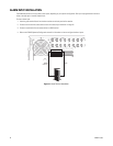
î Alarm Inputs: 16 normally closed inputs
ï= Camera Outputs: 8 or 16 BNC camera outputs
ñ Camera Inputs: 8 or 16 BNC camera inputs
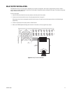
ó Relay Outputs: 16 normally open outputs
r Dual Display Card Switch and Outputs (optional): Switch selects VGA connector (down) or composite BNC (up) output
s Audio Inputs (optional): 8 or 16 channels
t RJ-45 Extended Peripheral Connector 4 (RS-422/RS-485 compliant)
u RJ-45 Extended Peripheral Connector 3 (RS-422/RS-485 compliant)
~í RJ-45 Extended Peripheral Connector 2 (RS-422/RS-485 compliant)
~â RJ-45 Extended Peripheral Connector 1 (RS-422/RS-485 compliant)
~ä BNC Programmable Analog Display Output
~ã Audio Input (standard): One miniature phone jack for line in
~å Audio Output (standard): One miniature phone jack for audio output
~ç Mic Input (standard): One 2-channel (right/left) miniature phone jack for line in
~é High-Speed USB 2.0 Ports: Two USB ports on the front and four on the back of the unit for connecting a USB mouse, keyboard, and
external JBOD device
~è Ethernet Adapter Port: 100 Mbps port
~ê VGA Monitor Output: 15-pin output
~ë 9-Pin Serial Port: COM1
Äí LPT1 Printer Port: 25-pin port
Äâ High-Speed USB 2.0 Ports: Two USB ports on the front and four on the back of the unit for connecting a USB mouse, keyboard, and
external JBOD device
Ää Keyboard (PS/2) Input
Äã Mouse (PS/2) Input
IN1 IN2 IN3 IN4 IN5 IN6 IN7 IN8 IN9 IN10 IN11 IN12 IN13 IN14 IN15 IN16
OUT16OUT15OUT14OUT13OUT12OUT11OUT10OUT9OUT8OUT7OUT6OUT5OUT4OUT3OUT2OUT1
9101112G313141516G4
1234G15678G2
9 101112 G 13141516 G
1234G5678G
RELAY OUTPUTSALARM INPUTS