


C2629M-E (7/09) 71
PV140-to-RS-422 Connection
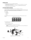
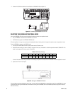
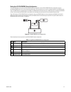
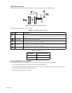
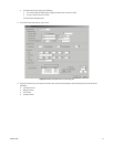
Figure 73 illustrates the cabling requirements to implement PV140 to RS-422 connectivity to the DX8100 RJ-45 port.
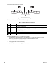
Figure 73. PV140 RS-232 to RS-422/485 Converter
Table M describes the PV140 RS-232 to RS-422 converter.
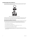
Connecting ATM/POS Devices using RS-422
To connect ATM/POS devices in a RS-422 configuration, refer to Figure 73 and Table M on page 71 and do the following:
1. Use the appropriate AVE cable to connect each additional VSI-PRO to an ATM/POS device.
2. Set up one PV140 RS-232 to RS-422 converter and user-supplied RJ-45 cable for each ATM/POS device. For installation instructions, refer
to the PV140 RS-232/422 Converter Kit Installation manual.
3. Insert the RJ-45 plug into ports 1 to 4 as required.
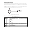
Table M. VSI-PRO DB9-to-DB9 Triport Cable
Item Part Description
ì DB9 (female) PV140 DB9 female connector that interfaces with the triport DB9 male connector. The VSI-PRO triport DB9
male connector pin assignments and the PV140 terminal wiring pin assignments are described in Table N on
page 71.
î Power supply PV140 power transformer provides 12 VDC.
ï Transmit data PV140 terminal TX+, which connects to the pin 8 (RX+) of the DX8100 RJ-45 connector. For information about
the DX8100 back panel, refer to Figure 11 on page 24.
ñ Transmit data PV140 terminal TX-, which connects to the pin 7 (RX-) of the DX8100 RJ-45 connector. For information about
the DX8100 back panel, refer to Figure 11 on page 24.
ó RJ-45 User-supplied RJ-45 connector that interfaces the ATM/POS device to DX8100 ports 1 to 4.
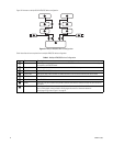
Table N. PV140 DB9 Pinouts
Triport DB9 Male User-Supplied RJ-45 Cable
Pin 2: RD Pin 2: RD
Pin 5: SGND Pin 5: SGND
ᕢ
ᕦ
ᕡ
ᕣ
ᕤ
ᕥ