


Diagnostic Software, Trouble Shooting and Test Instructions
EN 39DVD963SA 5.
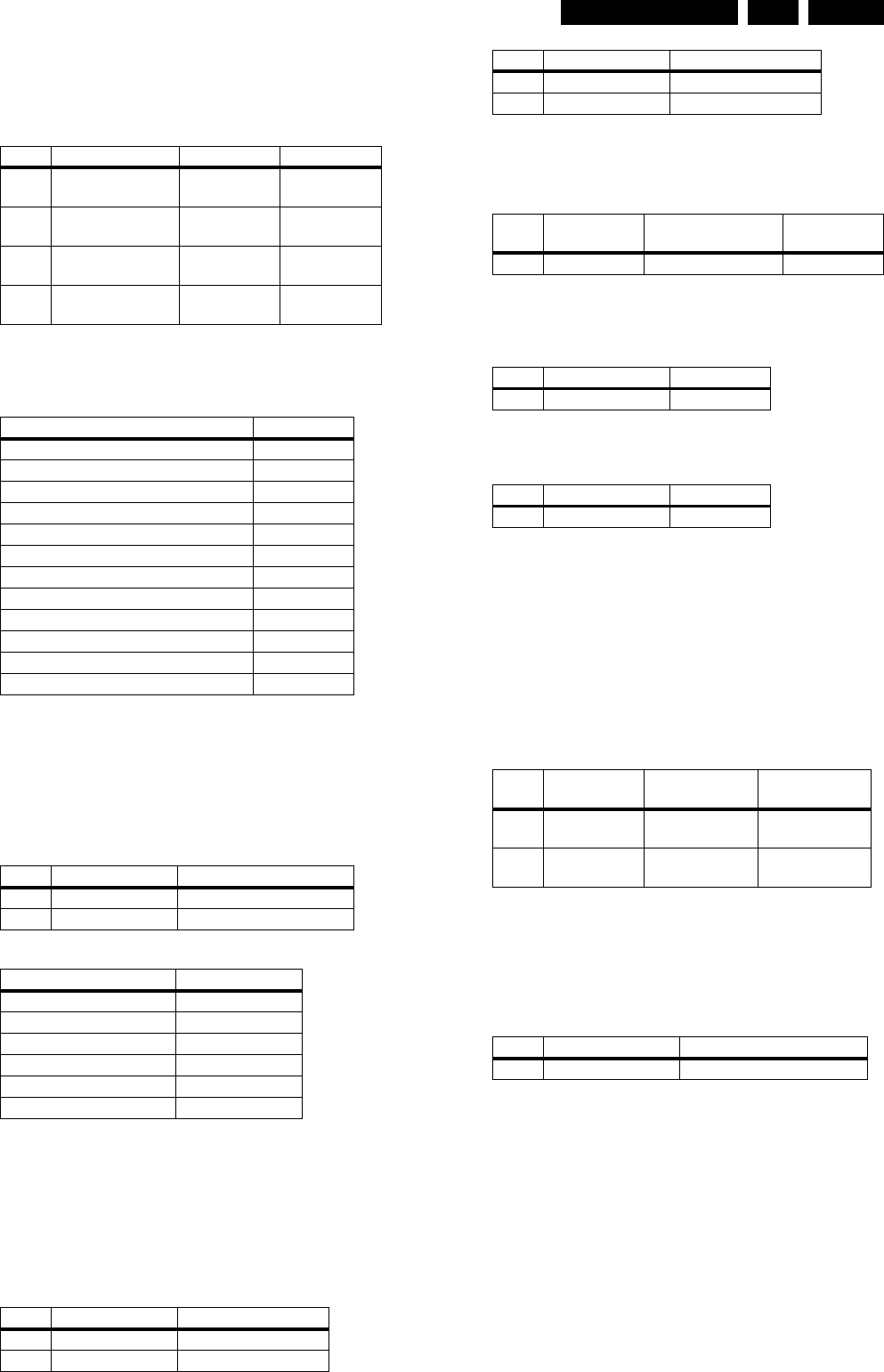
5.9.3 Audio DAC And Amplifier
Ensure that the Audio mute signal is OFF
To check the DAC and buffer amplifier,send the following
commands.
The audio signal ( sine or pink noise ) will also be present on
the digital output ( SPDIF ).This can be checked by connecting
digital signal to an amplifier with digital input.
Check the I2S and audio signal at the following testpoints:
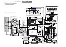
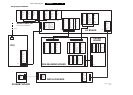
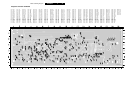
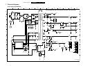
All waveforms can be refered to the A/V board schematic
diagram.
5.9.4 Video Output And Buffer Amplifier
Check DC output-level at all video cinch output : 1.0V DC ±
10%
Generate a color bar using the following software commands:
Check the video outputs at the following testpoints:
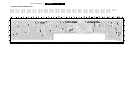
ll waveforms can be refered to the A/V board schematic
diagram.
5.9.5 Play and 16/9 Detection
Check DC voltage at S-VIDEO-CHROMA output (pin 4) with a
6k8 ohm load and SCART connector 1403 (pin 16) and change
the SCART0 and SCART1 input using the following
commands:
5.9.6 Kill Circuit
To check the functionality of the Kill circuitry,the audio outputs
has to be present by the following command:
Check the audio outputs at the audio cinch of the A/V and
SCART board: 1kHz tone.
Activate the Kill circuit by using the following command:
Check the audio outputs at the audio L/R cinch and SCART of
the A/V and SCART board respectively: No waveform
Switch off the kill circuit by using the following command:
Check the audio outputs at the audio L/R cinch and SCART of
the A/V and SCART board: 1kHz tone
5.9.7 Digital Silence
Digital silence is a signal from the audio DAC7301 (MFL,MFR)
and DAC7300 (MSR/MC),when there is no input to the audio
DAC, or when the player is in STOP/PAUSE mode, or during
disc changing track.
To check the MFL signal, use the following command and
check the voltage level at pin 41 of 7200:
5.9.8 Front Display
To check the segment display of the FTD, the following
command can be used. And for full detail description of the test,
refer to the chapter of “Diagnostic Software Player Script”
which can be found in chapter “Diagnostic Software
Description and Troubleshooting”
5.9.9 IR Receiver
Check at pin 22 of 7401 and observe if this line switches from
LOW (<0.3V) to HIGH (>4.5V) when pressing a key on a philips
RC5 or RC6 remote control
5.9.10 P50 Interface
P50 (or Easylink) is a bi-directional serial interface for
communication between video equipment. To check for the
functionality of the P50 Interface, refer to the chapter of
‘Diagnostic Software Player Script’ for full detail description.
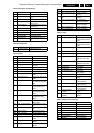
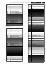
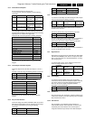
Ref.# Command Name Remarks Audio output
21a AudioSineOn Audio Sine
signal ON
Sine,1Khz on
stereo
---- Press stop button Audio Sine
signal OFF
No waveform
20a AudioPinkNoiseOn Audio
Pinknoise ON
Pink Noise on
6 channels
20b AudioPinkNoiseOff Audio
Pinknoise OFF
No waveform
Name Testpoint
PCM_LRCLK I112
PCM_SCLK I114
PCM_CLK I116
SDT1 I110
SDT2 I106
SDT3 I102
DIG_OUT I629
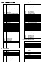
STEREO L/R OUT I510 / I520
FRONT L/R OUT I552 / I524
SURROUND L/R OUT I533 / I536
CENTRE OUT I530
SUB WOOFER L/R OUT I527
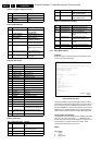
Ref.# Command Name Remarks
23a VideoColDencOn Colour DENC ON
23b VideoColDencOff Colourbar DENC OFF
Name Testpoint
GREEN_SCART I601
BLUE_SCART I600
RED_SCART I602
CVBS out_Mono I662
C_Mono I675
Y_Mono I667
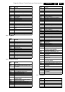
Ref.# Command Name Remarks
25a VideoScartLo Sends out 0V ± 0.5V
25b VideoScartMi Sends out 6V ± 10%
25c VideoScartHi Sends out 12V ± 10%
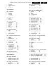
Ref.#
Command
Name Remarks Audio output
21a AudioSineOn Audio Sinewave ON 1kHz tone
Ref.# Command Name Remarks
19a AudioMuteOn Audio Mute On
Ref.# Command Name Remarks
19b AudioMuteOff Audio Mute Off
Ref.#
Command
Name Remarks KILL_LR signal
21a AudioSineOn Audio Sinewave
ON
LOW (<0.3V)
--- Press STOP
button
Audio Sine
signal OFF
HIGH (>4.5V)
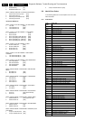
Ref.# Command Name Remarks
30a DispDisplay Turn ON local display
Ref.# Command Name Remarks