


Circuit Descriptions and List of Abbreviations
EN 85DVD963SA 9.
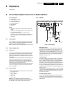
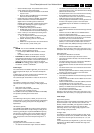
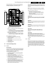
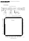
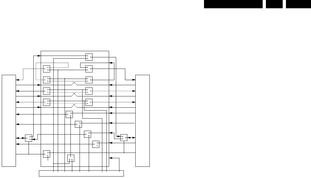
does not support this, an external circuit (two bi-directional
switches, named switch "1" and switch "2") is added. The Y-
and CVBS-components also share the same pins.
Figure 9-13 SCART switching circuitry
• Switch "1" is controlled by the FB (Fast Blanking) pin (pin
16) of SCART2 (TV SCART):
– If the FB line is low, C is input on the B/C of SCART2.
– If the FB line is high, B is output on the B/C of SCART2.
• Switch "2" is controlled by the FB (Fast Blanking) pin (pin
16) of SCART1 (AUX SCART):
– If the FB line is low, C is output on the B/C of SCART1.
– If the FB line is high, B is intput on the B/C of SCART1.
We can distinguish four situations:
1. DVD player is ON, DVD is active (DVD mode):
NO LOOP-TROUGH.
2. DVD player is ON, DVD is not active (TV mode):
LOOP-TROUGH.
3. DVD player is ON, external source becomes active:
LOOP-TROUGH.
4. DVD player is in STBY:
LOOP-TROUGH.
9.7 Control and Display Panel
9.7.1 Control
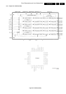
Slave processor
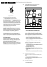
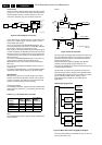
The key component on this board is the (slave) microprocessor
(item 7401). It runs on an 8 MHz system clock generated with
a ceramic resonator (item 1119) and has a reset circuit (item
7105) that is triggered by the +5Vstb voltage.
The start-up sequence is as follows:
1. The required IC voltage is the +5Vstb, which is present
during Standby Mode.
2. When the RESET circuit (item 7105) is triggered by the
+5Vstb, the slave uP initialises.
3. This will set the STDBY_CONTROL signal to LOW, which
will switch on the 12V and subsequently the +3V3.
4. Once these voltages are provided, the host uP (on the
mono board) will reset (via reset circuit around item 7412
on the mono board, diagram M4).
5. Now, the host uP will initialise, and indicate the slave uP to
activate the Standby Mode (STBY_CONTROL) signal.
6. The player wakes up from the Standby Mode when any
button is pressed on the front panel, or when the 'Power'
button is pressed on the Remote Control.
Also, when going to Standby, the slave processor will reset the
host processor. When the slave processor receives the correct
IR (or key) code to leave the Standby mode, it resets the host
processor.
Note: The slave uP will not reset successfully, if the 8MHz
clock oscillator has not stabilised (check on pin 8 of IC7101).
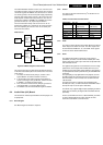
Other slave processor functions are:
• Generation of a scanning grid for the keys,
• Generation of the display grid and segment scanning,
• Generation of square signal to generate the filament
voltage for FTD display,
• Inputs for RC5/6 and P50 (P50 controller is build in).
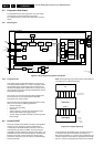
Standby LED
Transistor 7104 drives the Standby LED. When the STBLED
signal from the slave processor is ‘high’ (pin 14), the LED is
‘off’.
Key Matrix
When a key on the local keyboard is pressed, the signal at the
scanning pins of the microprocessor (pins 34, 35, 36 and 37)
go from +5 V to 0 V.
IR Receiver
The IR controller in the slave processor handles both RC5 and
RC6 signals (input on pin 22). The logic is +5 V for ‘high’ and 0
V for ‘low’.
Status LEDs
The four status LEDs (SOUND, AUDIO DIRECT, UP-
SAMPLING, and P-SCAN) are controlled by the slave
processor.
P50 Interface
P50 (or Easylink) is a bi-directional serial interface for
communication between video equipment. For European sets,
this communication goes via pin 10 of the SCART connector,
while for other regions (when present), this is a cinch
connector. The slave processor controls the P50 bus (via pins
11 and 20).
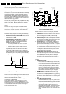
9.7.2 Display
Because these DVD players have an AC display (FTD) and a
DC supply, an AC voltage is created by the microprocessor
The slave processor has an internal square signal generator
(42 kHz, duty cycle 45/55), to generate the AC filament voltage.
This square voltage is amplified (by TS7106 and 7109) and
decoupled (C2138 and C2143) before it is applied to the
display. The necessary voltage of -32 V comes directly from the
PSU.
CL 26532105_030.eps
300802
STV6410
SCART to TV
SCART2
A/V Board
C
0 or 5V
4/3;16/9
select
Blanking
Switch
BI
2
CGRY CVBS
1
B/C
SB
G
2
R/C
L_out
L_in
Fast
Blanking
L
R
1300
R_out
R_in
Y/CVBS-out
Y/CVBS-in
AUX-SCART
SCART1
B/C
SB
G
R/C
L_out
L_in
Aux Fast
Blanking
R_out
R_in
Y/CVBS-out
Y/CVBS-in