


Circuit Descriptions and List of Abbreviations
EN 87DVD963SA 9.
9.9 IC Data
In this paragraph, the internal block diagrams and pinning are
given of ICs that are drawn as 'black box' in the electrical
diagrams (with the exception of 'memory' and 'logic' ICs).
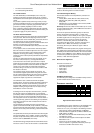
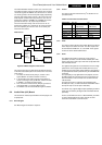
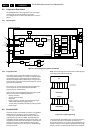
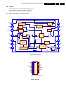
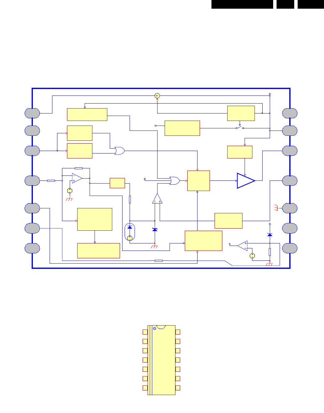
9.9.1 Diagram Power Supply: TY72011P2 (item 7130
Figure 9-14 Block Diagram
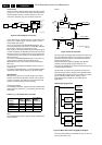
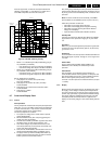
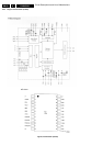
Figure 9-15 Pinning
UVLOh = 15V
UVLOl = 7.2V
DEMAG ?
2.5V
Over Current
Protection (OCP)
V(-) < 1.5V
More than 128ms?
Toff = f (Verr)
Max Toff = f (Ct)
VCO Feedback
Startup
--> protection circuitry
Internal Vcc
1
3
4
5 10
11
12
14
Internal regulator
HV
Demag
FB
Ct Gnd
Isense
Vcc
Verr max = 3V
Verr min = 10mV
DRV
Driver
Last pulse of
demag after 4µs
1/3
1V
Rf
Ri
Current comparator
.
Flip-Flop
250mV clamp
250mV - 1V max setpoint
Clock
R
D
Q
Verr
Internal Clamp
Over Voltage
Protection (Vcc > 41V?)
200ns L.E.B
2
NC
NC
OVP
6
7
4x10V zener
Vcc pin13
Vcc pin8
500
OVP
OVP
60mV
20k
13
9
8
NC
NC
PIN CONNECTIONS
1
2
3
4
5
6
78
9
10
11
12
13
14
HV
Demag
FB
Ct
OVP
Isense
GND
Vcc
Drive
nc
nc
nc
ncnc