


Circuit Descriptions and List of Abbreviations
EN 84 DVD963SA9.
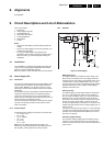
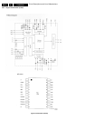
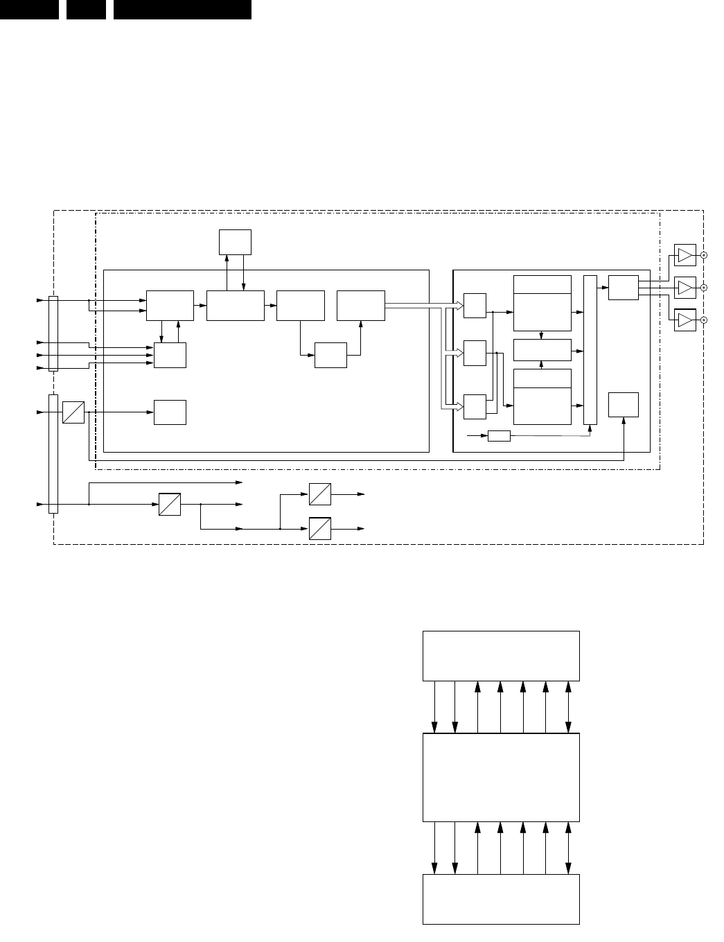
9.5 Progressive Scan Board
The DVD963SA series offer progressive scan YUV outputs,
and the option to select the interlace YUV output
by a sliding switch on the board (selectable at the rear of the
player).
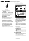
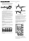
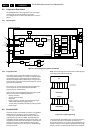
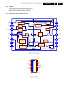
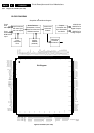
9.5.1 Block diagram
Figure 9-11 Block diagram Progressive Scan Board
9.5.2 Progressive YUV
This creates a picture signal with double the scan lines of a
conventional interlaced picture, to create a noticeably sharper
and smoother image. It offers higher picture resolution and
eliminates virtually all motion artefacts. Even on large screens,
the progressive scan lines are barely noticeable and it reduces
picture flickering significant.
Two new IC's are used: the Faroudja FLI2310 Digital Video
Format Converter, and the Analog Devices ADV7300
Progressive Scan Video Encoder.
This board also offers the Digital Crystal Clear feature, which
allow you to fine-tune the following parameters:
• Gamma correction.
• Chroma and Luma delay.
• Sharpness.
• DCDi: to produce a smooth and natural looking image
without visible artifacts (like jagged edges).
• True life: brings out details in the picture, producing a more
life-like image.
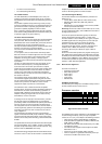
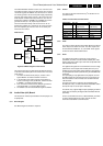
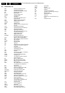
9.6 Double SCART
This board consists of two SCART connectors and a SCART-
switch (item 7501, STV6410), which is controlled by I
2
C.
In a P50 player with double SCART connectors, video and
audio loop-through must be available. This loop-through is
controlled by the P50 commands, which are send via pin 10 of
the SCART connector. When the DVD player is in standby, the
loop-through is active. During standby, the display (slave)
processor is active (takes over the I
2
C-bus), and will manage
the P50 commands.
Note: The loop-through only functions when the DVD-player is
in standby (NOT in low power standby)
Figure 9-12 Loop-through set-up
The B component (from RGB) and the C component (from Y/
C) share the same pin on the SCART connector (pin 7).
Because the B-signal is an "up-stream" signal (towards the TV)
and the C-signal is a "down-stream" signal (towards the VCR),
this pin 7 must be a bi-directional pin. Because the STV6410
CL 26532105_028.eps
300802
PROGRESSIVE SCAN BOARD
PROGRESSIVE YUV
FORMAT CONVERTER
DIGITAL VIDEO
SDRAM
7101
7100
1000
1202
DIGITAL
YUV
DATA
H_SYNC
V_SYNC
27M_CLOCK
Noise Reducer,
Deinterlacer, Frame
Rate Converter and
SDRAM interface
Input Processor
with Auto Sync
and auto Adjust
Port 2
8-bit
656 Input
Vertical and
Horizontal
Scalers
16/20/24-bit
RGB/YCrCb
Digital Outputs
RGB/YCrCb
Analog Outputs
Clock
Generation
PLLs
Vertical and
Horizontal
Enhancers
HD
Demux
Timing
Gen.
CLK
PLL
SD
Demux
Port 1
8/16/24-bit
RGB/YCrCb
Input
Control
Interface
Control
Interface
PROGRESSIVE ENCODER
7100
Color Control
Brightness
Gamma
Programmable Filters
SD Test Pattern
HD Test Pattern
Color Control
Adaptive Filter CTRL
Sharpness Filter
Standard Defenition
Control Block
Programmable
RGB Matrix
High Defenition
Control Block
I
2
C
+5VD
+5VA
+3V3A
+3V3D
5V
3V3
5V
3V3
3V3
1V8
3V3
2V5
1V8
2V5
7301
7300
Y
7301
Pb/Cb
7302
Pr/Cr
7303
O
V
E
R
S
A
M
P
L
I
N
G
DAC
Output
Processor with
Sync Generation
and DACs
CL 26532105_029.eps
290802
VCR/STB/etc
TV
DVD Player
SCART2
SCART1
Control lines
are not shown
Blue is up
C is down
Blue (from RGB) is up
C (from Y/C) is down
CVBS
or Y
TV
CVBS
or Y
down
CVBS
or Y
up
CVBS
or Y
up
R
or C
R
or C
G
G
B
or C
B
or C
Audio
TV
Audio
down
Audio
up
Audio
VCR