


Circuit Descriptions and List of Abbreviations
EN 78 DVD963SA9.
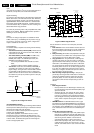
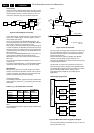
Figure 9-2 TL431
This reference component has two functions:
• A very stable and accurate reference diode
• A high gain amplifier.
When the output voltage increases (due to a reduction in the
load), the voltage across R
SENSE-2
(R3290/R3291) increases to
above the internal reference voltage of 2.5V. The TL431 will
conduct and the current through the opto-coupler will increase.
This results in an increase of the voltage at pin 4 of IC1, which
will reduce the 'on' time of Q1 (FET 7125). In the event of an
output voltage decrease (due to an increase in the load), the
control circuit will operate in the opposite way.
Primary Current Sensing
The current through FET Q1 will result in a voltage drop across
RSENSE-1 (R3120-23). This line goes to pin 11 of IC7130,
which is the current sense input. The higher the input voltage,
the more the primary current is limited. In this way, the
maximum output power of the power supply is limited.
Under-voltage Protection
If the supply voltage at pin 13 of IC7130 drops below 7.2V
(typical), e.g. due to a shorted secondary voltage or excessive
load, the drive pulse at pin 12 is disabled and the controller will
switch 'off'.
Over-voltage Protection
An internal over-voltage protection circuitry continuously
monitors the Vcc pin. If, after start-up, this voltage exceeds
40V, the internal latch circuit is triggered, the output buffer is
disabled, and the SMPS goes into over-voltage protection.
Now a complete restart sequence is required.
Note: If the event of the over-voltage situation remains present,
the SMPS will go in sequence of protection, start-up, protection
and the cycle repeats. This effect is highly audible.
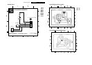
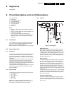
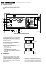
9.3 Loader/Mono Board (for diagrams see
SD4.00SA_CH Service Manual)
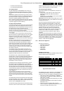
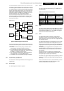
Figure 9-3 Block Diagram Loader/Mono board
The SD4.00_SA_CH (SACHI_4) is the 2nd generation Philips
Architectural Standard Design of SACD mono board based on
Furore 2, and will be used in the new generation of SACD
players. It is designed in a multi-task way so that it can support
the following optional main functions:
• SD4.00_SA_CH: Support SACD player with 5-disc
changer.
• SD4.00_SA: Support SACD player with single-disc.
• SD4.00_CH: Support DVD player with 5-disc changer but
without SACD playback.
• SD4.00_SA_I
2
C: Support SACD player with single-disc
and I
2
C slave.
The SD4.00_SA_CH (SACHI_4) module consist of the
following key components:
1. OPU: Mercury 2 Loader VAL6011/14 (slim type) for a
single-disc SACD player, or DVD VAM6001/14 mechanism
for a 5-disc SACD changer.
2. Front-end: M2 Basic Engine.
3. Back-end: DVD Host Processor STi55xx and Furore 2
SACD DSD/DST decoder.
4. Power supply: To convert the PSU voltages to the correct
values.
5. Reset circuit: This circuit that the booting of the several
devices on the mono board takes place in the correct order.
9.3.1 The Optical Pick-up Unit (OPU)
The Mercury 2 Loader has an optical unit consisting of two
lasers:
• One for CD with a wavelength of 780 nm.
• One for DVD with a wavelength of 650 nm.
The TZA1033 (item 7105) controls the data from these lasers,
and the supply to them.
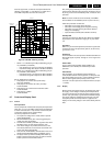
9.3.2 Front-end: the Servo Part
The front-end consists of:
• The Loader interface
A
2.5V
R
K
CL 96532065_071.eps
130799
CL 26532053_022.eps
260402
Loader
Module
Interface
Loader-interfaceDVDalas2+
FURORE 2
Audio
OthersVideo
Iguana
(front-end
processor)
STi55XX
(back-end
processor)
HF
Buffer
Program
Memory
SMI
(SDRAM)
EMI
(FLASH)
FRONT-ENDBACK-END
I
2
S S2B
PCM
HF