


Circuit Descriptions and List of Abbreviations
EN 83DVD963SA 9.
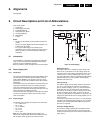
The SACD DSD/DST decoder Furore 2 uses 1.8V for its core
and analogue portion, and 3.3V for its interface. The on-board
1.8V linear regulator LF18ABDT and 3.3V linear LD1117DT33
are used to generate 1.8V and 3.3V power supply respectively.
The back-end section mainly uses the 1.8V or 2.5V and 3.3V,
which depend on which back-end processor is used. The on-
board linear regulators LF25ABDT or LF18ABDT are used to
generate the 2.5V (or 1.8V) required by the STi55xx.
The front-end section mainly uses the 5V and 12V. An on-
board linear regulator LD1117DT33 can be used to generate
the 3.3V required by the front-end. The 12V is used by the
motor and servo drivers.
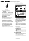
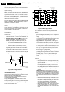
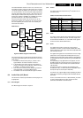
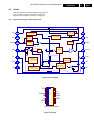
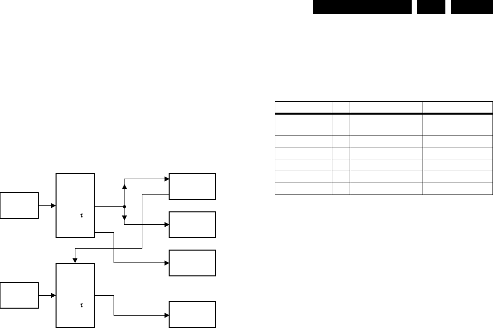
Reset Circuit
Figure 9-10 Block diagram of reset circuit
This reset circuit takes care that booting the different devices
on the mono board takes place in the correct order. The correct
reset order is:
1. The Power On Reset circuit (delay t1) creates a reset
signal 'RESETn' to reset the STi55xx and Furore .
2. In the meantime, the Power On Reset circuit (delay t1)
creates a reset signal 'CLK_STBCTRL', which is inverted
to 'RESETn', to enable the Clock Factory.
3. Then, the Power On Reset circuit (delay t2) generates a
reset signal 'RES_P' to reset the Basic Engine.
4. The STI55xx can now reset the Basic Engine via 'RSTN'.
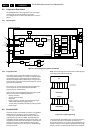
9.4 Audio/Video (A/V) Board
This board is the interface panel between the DVD-player and
its peripherals.
9.4.1 Block diagram
See Block diagram A/V Board in chapter 6.
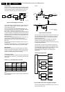
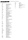
9.4.2 Control
The control of the A/V board is done by I
2
C-decoder IC7107
(see table below):
Table 9-2 Control lines overview IC7107
9.4.3 Video
The analogue video signals from the Mono Board are buffered
before they are fed to the A/V board. The video outputs from
the A/V Board are RGB/YUV, YC, and CVBS. These signals
are also fed to the double SCART board.
9.4.4 Audio
The digital audio signals for Surround, Centre and LFE
(subwoofer) are fed to a 6-channel DAC CS4362 (item 7300,
48-pin LQFP) for the audio output. This DAC accepts both DSD
and PCM data streams.
The digital audio signals for Front and Stereo are fed to a high
performance current output DAC AD1955 (item 7301) via a
multiplexer (item 7200) which selects either the direct PCM or
an upsampled data stream (determined by the UPSAMPLING
control line.
The Upsampling is only applicable for CD playback, and the
AD1895 sample rate converter (item 7201) converts the 44.1
kHz/16 bit audio to various formats such as 96 kHz/24 bit or
192 kHz/24 bit.
The bit and word clock, required by the upsampling DAC
AD1955 (item 7301), are derived from the 24.576 MHz master
clock (item7103) via counter (item 7204/7205).
The S/PDIF, only supports digital output upsampling of 96 kHz/
24 bit and is encoded by the digital audio transmitter AK4103
(item7203).
There is a control line from IC7107, called CENTRE_ON, which
is used to switch between the centre channel and front
channels for both SACD- and DVD modes.
RES_P
CLK_STBCTRL
CL 26532053_018.eps
260402
STi55xx
Power On
Reset
Circuit
Delay 1
Furore 2
Clock Factory
Low Voltage
Detection
4.5V
Low Voltage
Detection
4.5V
Basic Engine
Power On
Reset
Circuit
Delay 2
RSTN
RESETn
Description Pin Hi Lo
CLK_SEL 12 External clock
(DSD stream)
Internal clock
(PCM stream)
UPSAMPLING 11 No upsampling Upsampling
DAC_RESET 10 Normal Reset
CENTER_ON 9 Off On
SPDIF-MUTE 5 Mute No mute
192k/96k 4 192k PCM 96k PCM