


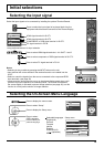

AUDIO
PC IN
9
Connections
1
678
3
9
45
10
15 14 13 12 11
2
Notes:
Due to space limitations, occasionally you may have trouble connecting Mini D-sub 15P cable with ferrite core to PC input
Terminal.
With regard to the typical PC input signals that are described in the applicable input signals list (see page 49), adjustment
values such as for the standard picture positions and sizes have already been stored in this unit. You can add up to eight
PC input signal types that are not included in the list.
Computer signals which can be input are those with a horizontal scanning frequency of 15 to 110 kHz and vertical
scanning frequency of 48 to 120 Hz. (However, the image will not be displayed properly if the signals exceed 1,200 lines.)
The display resolution is a maximum of 1,440 × 1,080 dots when the aspect mode is set to “4:3”, and 1,920 ×
1,080 dots when the aspect mode is set to “16:9”. If the display resolution exceeds these maximums, it may not
be possible to show fine detail with sufficient clarity.
The PC input terminals are DDC2B-compatible. If the computer being connected is not DDC2B-compatible, you
will need to make setting changes to the computer at the time of connection.
Some PC models cannot be connected to the set.
There is no need to use an adapter for computers with DOS/V compatible Mini D-sub 15P terminal.
The computer shown in the illustration is for example purposes only.
Additional equipment and cables shown are not supplied with this set.
Do not set the horizontal and vertical scanning frequencies for PC signals which are above or below the specified
frequency range.
Component Input is possible with the pin 1, 2, 3 of the Mini D-sub 15P Connector.
To use sync input VBS signals, use the connector which incorporates a 75-ohm termination resistance and which
is available on the market, for the connection of the HD connector where the VBS signals are to be input.
Change the “Component/RGB-in select” setting in the “Setup” menu to “Component”
(when Component signal connection) or “RGB” (when RGB signal connection). (see page 38)
•
•
•
•
•
•
•
•
•
•
•
•
•
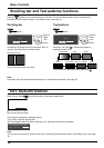
Signal Names for Mini D-sub 15P Connector
Pin Layout for PC Input
Terminal
PC Input Terminals connection
COMPUTER
Conversion adapter
(if necessary)
Mini D-sub 15p
RGB
PC cable
Stereo plug
Audio
Connect a cable which matches
the audio output terminal on the computer.
Pin No. Signal Name Pin No. Signal Name Pin No. Signal Name
1
R (PR/CR)
6
GND (Ground)
11
NC (not connected)
2
G (Y)
7
GND (Ground)
12
SDA
3
B (PB/CB)
8
GND (Ground)
13
HD/SYNC
4
NC (not connected)
9
+5 V DC
14
VD
5
GND (Ground)
10
GND (Ground)
15
SCL
(Male)
(Female)