Connecting up
02
16
En
Easy connections
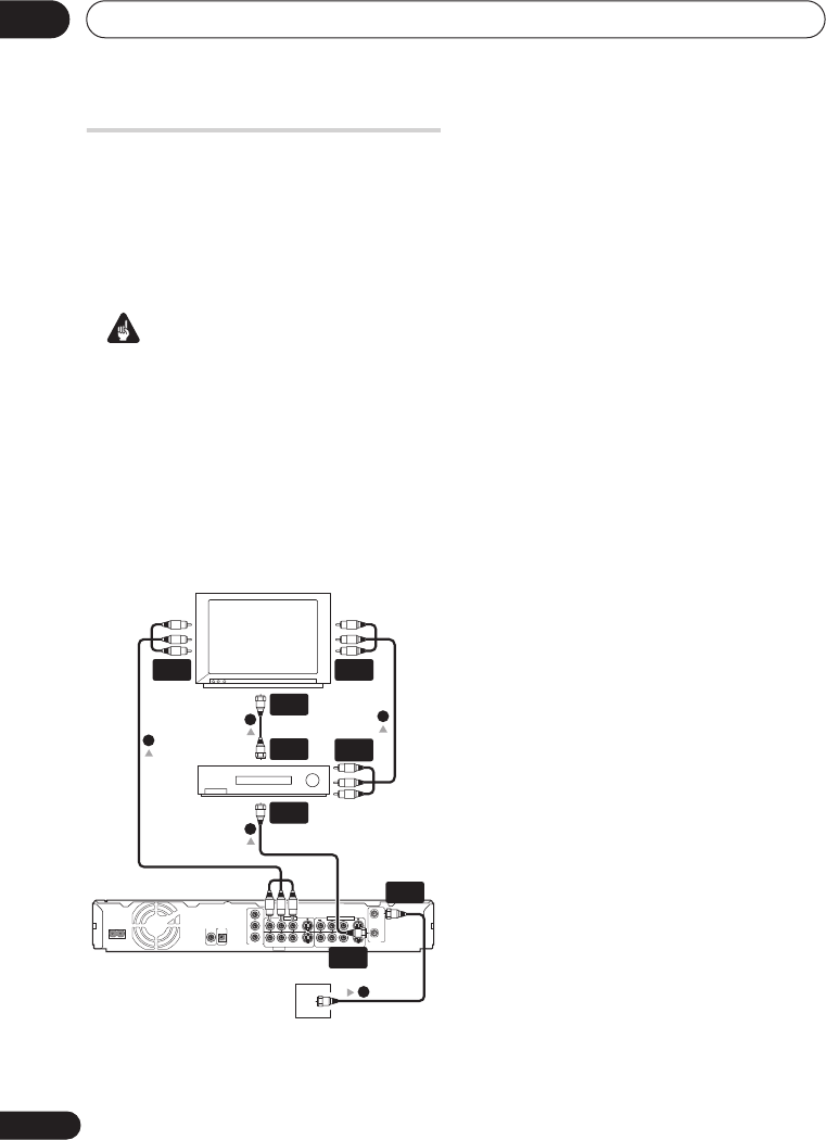
The setup described here is a basic
configuration that allows you to record TV
programs on both this recorder and your
VCR. When watching recordings from this
recorder, set your TV to input 1; switch to
input 2 to watch a video playing in the VCR.
Important
• This recorder is equipped with copy
protection technology. Do not connect
this recorder to your TV via a VCR (or your
VCR via this recorder) using AV cables,
as the picture from this recorder will not
appear properly on your TV.
• Before making or changing any rear
panel connections, make sure that all
components are switched off and
unplugged from the wall outlet.
1 Connect your TV antenna/cable TV
outlet to the ANTENNA IN (RF IN) jack on
this recorder.
2 Use an RF antenna cable (one is
supplied) to connect the ANTENNA OUT
jack on this recorder to the antenna input
on your VCR.
• If you are not connecting a VCR in the
chain, connect this recorder directly to
your TV and skip the next step.
3 Use an RF antenna cable to connect
the antenna output on your VCR to the
antenna input on your TV.
4 Connect the AUDIO and VIDEO
OUTPUT jacks (1 or 2) to a set of audio/
video inputs on your TV.
Use the supplied three-pin audio/video
cable. It is color-coded to help you match
them up (red/white for the right/left audio
connections and yellow for video in/outs).
Make sure you match up the left and right
outputs with their corresponding inputs for
correct stereo sound.
5 Connect your VCR to your TV (A/V IN
2 above) using a set of audio and video
cables.
• See the following page if you want to use
S-video or component video cables for
the video connection.
AC IN
S-VIDEO
VIDEO
AUDIO
L
R
OUTPUT 2
COMPONENT
VIDEO OUT
Y
P
B
P
R
ANTENNA
IN
OUT
COAXIAL
IN
CONTROL
DIGITAL
OUT
OUTPUT 1
VIDEO
AUDIO
L
R
INPUT 3
OUTPUT 1
INPUT 1/AUTO START REC
S-VIDEO
TV
VCR
Antenna/cable TV
wall outlet
ANTENNA
IN
ANTENNA
OUT
ANTENNA
IN
ANTENNA
OUT
ANTENNA
IN (RF IN)
A/V
IN 1
A/V
IN 2
A/V
OUT
1
2
3
4
5
DVR640H_RLT_EN.book 16 ページ 2006年4月11日 火曜日 午後12時26分


