


42
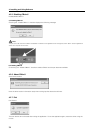
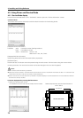
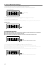
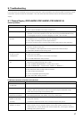
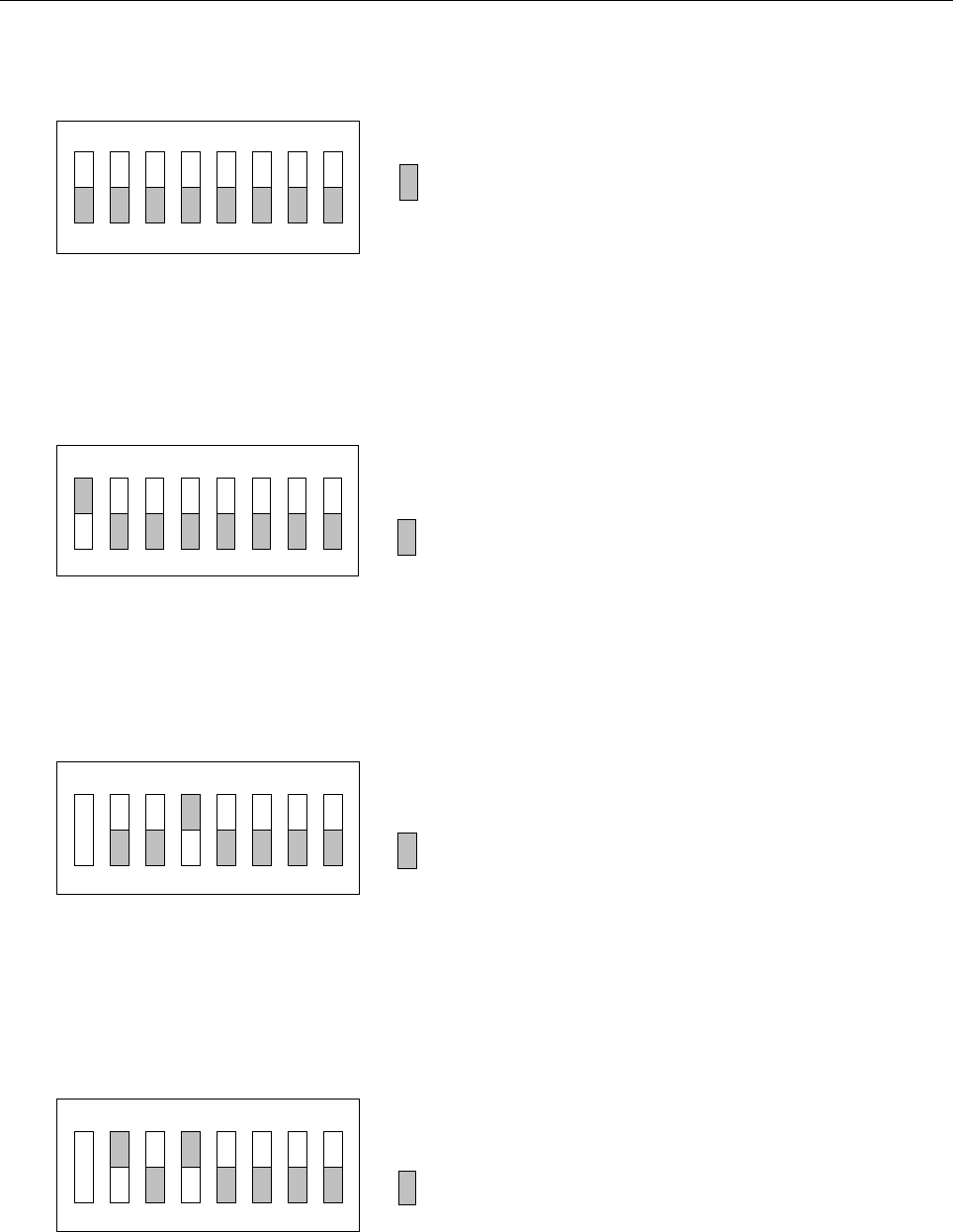
The test board A (LED) in the device is provided with 8-bit DIP switches (SW1).
DIP switch settings are read only when the device is powered up and their values stay the same.
: Factory default setting
(All off)
12
34
56
7
8
ON
Factory default status
* Bits 5 to 8 should alwa
y
s be set to OFF.
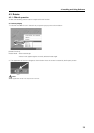
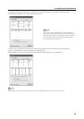
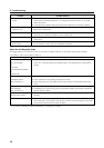
The following operations can be performed by changing DIP switch settings as shown below.
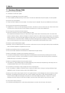
a) To lock device in the NORMAL mode
This setting overrides the mode selector switch [PEN] or [NORMAL] on the rear panel of the device and locks it in
NORMAL mode.
: Set side
12
34
56
78
ON
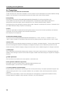
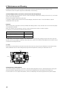
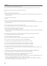
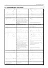
b) To make waveform observations
¶ This setting locks the device in low scan mode (all scan) suitable for waveform observation using an oscilloscope.
¶ The touch panel input functions do not operate in this mode.
¶ The power indicator on the device front panel blink continuously in approximately 0.5 second cycles.
: Set side
Bits that are not indicated can be set to any value.
1234 5678
ON
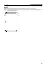
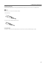
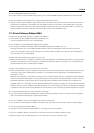
c) To make observations of infrared LED light emitting status using a CCD camera
¶ This setting performs a slow scan in approximately 1 second cycles. (Locked ultra low scan mode)
¶ The light emitting status of infrared LEDs can be observed in a dark room, but this depends on the camera used.
¶ The touch panel input functions do not operate in this mode.
¶ The power indicator on the device front panel blinks continuously in approximately 1 second cycles.
1234 5678
ON
: Set side
Bits that are not indicated can be set to any value.
6. Internal DIP Switch Settings