Graphics contained within this publication are for representation only.
Other Information
56 Chapter 8
Graphics contained within this publication are for representation only.
Other Information
Chapter 8 57
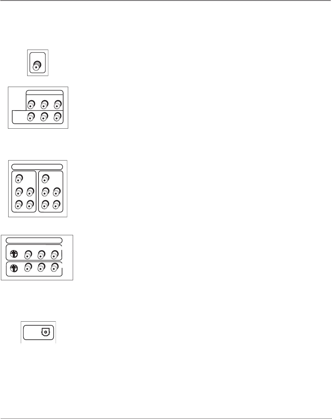
Explanation of Jacks (in alphabetical order)
This section describes the jacks you can use to make connections. There are several ways to connect components to your TV.
ANTENNA/CABLE Lets you connect a coaxial cable to receive the signal from the antenna, cable, cable
box, or if using the examples on pages 5-11, a VCR.
AUDIO/VIDEO OUTPUT
AUDIO/VIDEO OUTPUT Lets you connect an amplier or audio receiver for improved sound quality
or an external video monitor.
• FIXED AUDIO L/R Provides xed-level audio output from the TV. This audio output is ideal for
connecting an A/V receiver when you want to control the volume through the A/V receiver.
• VARIABLE AUDIO Provides variable-level audio output. Volume levels are controlled by the
volume controls on the TV and remote control.
• SUBWOOFER Provides lower bass audio frequencies from the TV to a subwoofer.
Note: If you’ve connected a subwoofer, make sure you set the External Subwoofer option in the
Sound menu. Go to page 43 for instructions.
COMPONENT INPUTS Lets you connect a component video source, such as a VCR.
• CMP1 Y PB PR (Component Video) Provides optimum picture quality because the video is
separated into three signals. Use three video-grade cables for the connection. When using CMP1 Y
PB PR, make sure to connect left and right audio cables to the CMP1 L and R Audio Input jacks.
• CMP1 L (Audio) Provides left audio connection. The left audio connector is usually white.
• CMP1 R (Audio) Provides right audio connection. The right audio connector is usually red.
• CMP2 Y PB PR, and L and R Audio Allows you to connect a second component video source.
Their description is the same as CMP1 above. When using CMP2 Y PB PR, make sure you connect
the left and right audio cables to the CMP2 Audio jacks.
COMPOSITE INPUTS Lets you connect another component such as a VCR, DVD player, or laserdisc
player. Its AUDIO jacks are the same as described for CMP1 above.
• VID1 S-VIDEO Provides better picture quality than the video jacks (VID1 and 2 Video) because
the color part of the picture is separated from the black and white part of the picture. When using
VID1 S-VIDEO, make sure to connect left and right audio cables to the VID1 L/MONO and R Audio
Input jacks.
• VID1 V (Video) Provides composite video connection. The video connector is usually yellow.
• VID2 S-VIDEO, V and L/MONO and R Audio Allows you to connect a component such as a VCR,
DVD player, or laserdisc player. Their description is the same as VID1 above.
Note: For each VID jack group (VID1 and VID2), you may connect either an S-Video or Video cable.
Do not connect both at the same time in either of the VID jack groups.
DIGITAL AUDIO OUTPUT Lets you connect a Dolby Digital receiver to your TV/DVD, if your receiver
has an optical input. Use an optical cable (or SPDIF cable) to connect your TV/DVD to the receiver for
theatre-quality sound. Go to page 41 for more information on digital audio.
Note: This TV/DVD’s OPTICAL DIGITAL OUT jack fully complies with the international standard
governing this type of jack (IEC958), and is designed for connection to a Dolby Digital (AC-3® or
PCM) receiver or Dolby Digital (AC-3 or PCM) decoder. Older equipment, some of which is not fully
compliant with IEC958, may not be compatible with the Dolby Digital bitstream. Such a connection
using anything other than Dolby Digital AC-3 or PCM receiver or decoder could create a high noise
level, causing damage to headphones or speakers.


