


5
DVD-R4000
Setting up
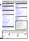
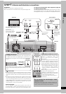
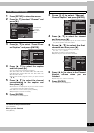
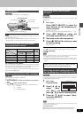
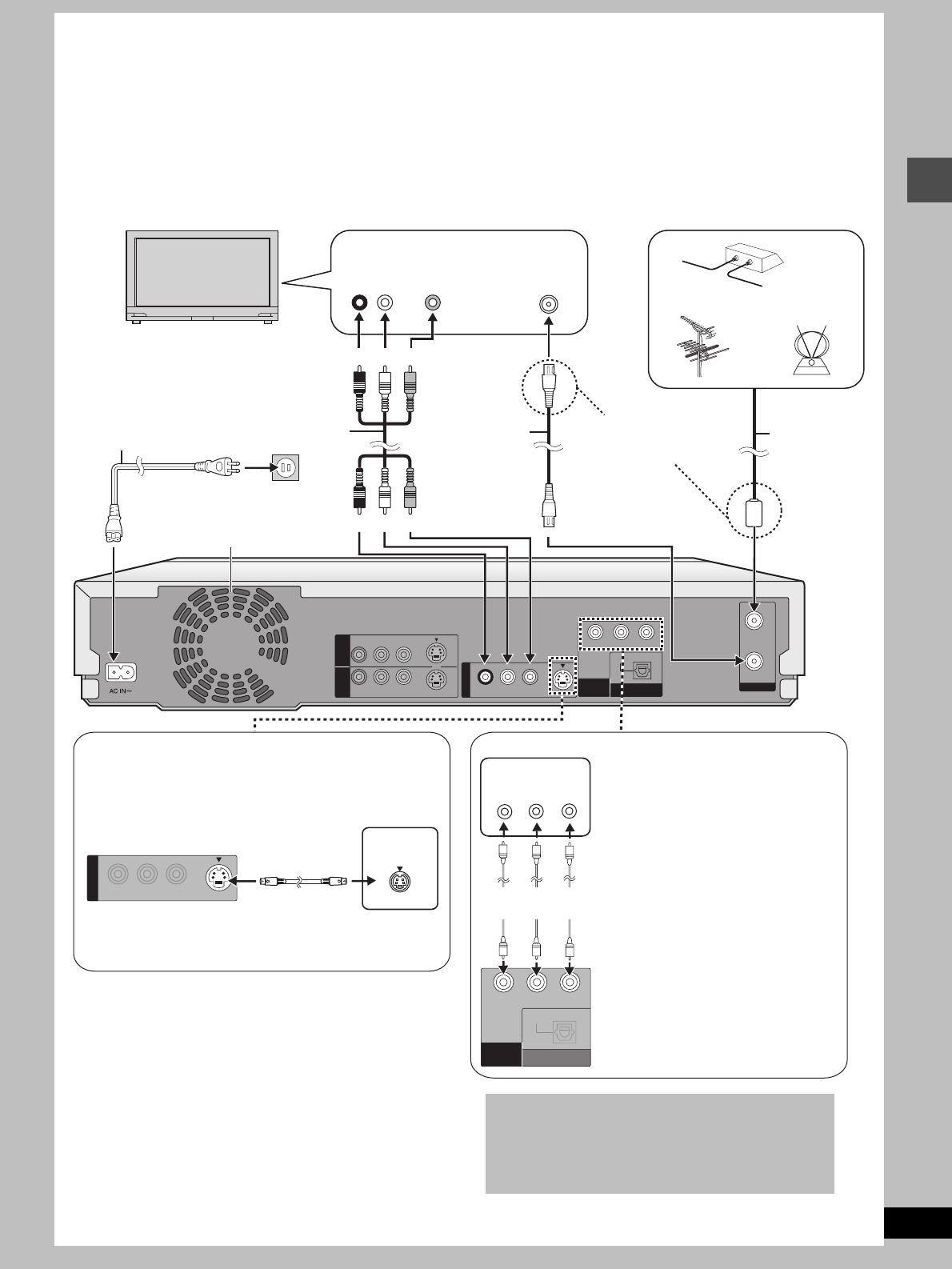
STEP 1 Antenna and television connections
Preparation
≥Refer to the television’s operating instructions.
≥Turn the television off and disconnect its AC power supply cord.
To enjoy sound through other audio equipment (
➜
page 42)
To enjoy progressive video
Connect to the component video(480P) input terminals on a televi-
sion compatible with this unit’s copy guard system. (Video will not
be displayed correctly if connected to an incompatible television.)
R-AUDIO-L
VIDEO
OPTICAL
DIGITAL AUDIO OUT
(PCM/BITSTREAM)
OUT
R-AUDIO-L
R-AUDIO-L
VIDEO
VIDEO
S-VIDEO
S-VIDEO
(L3)
(L1)
IN 1 IN 3
S-VIDEO
COMPONENT
VIDEO OUT
(480P/480I)
YPB PR
VHF/UHF
RF IN
RF OUT
AUDIO
IN
R L
VIDEO
IN
VHF/UHF
RF IN
IN
S VIDEO
COMPONENT
VIDEO IN
Y
P
B
PR
R-AUDIO-L
VIDEO
OUT
S-VIDEO
OPTICAL
DIGITAL AUDIO OUT
(PCM/BITSTREAM)
COMPONENT
VIDEO OUT
(480P/480I)
YP
B
P
R
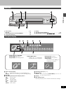
COMPONENT VIDEO OUT terminal
These terminals can be used for either
interlace or progressive output and
provide a purer picture than the S-VIDEO
OUT terminal.
Connection using these terminals outputs
the color difference signals (P
B/PR) and
luminance signal (Y) separately in order to
achieve high fidelity in reproducing colors
.
≥The description of the component video
input terminals depends on the televi-
sion or monitor (e.g. Y/P
B/PR, Y/B-Y/R-Y,
Y/C
B/CR). Connect to terminals of the
same color.
≥After making this connect, change the
black level for a better picture
(➜page 47, Video–Black Level Control).
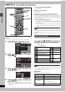
S-VIDEO OUT terminal
The S-VIDEO OUT terminal achieves a more vivid picture than
the VIDEO OUT terminal by separating the chrominance (C)
and luminance (Y) signals. (Actual results depend on the tele-
vision.)
When making this connection, ensure you connect the audio
cables to the corresponding audio input terminals on the tele-
vision.
When making this connection, ensure you
connect the audio cables to the
corresponding audio input terminals on
the television.
To the antenna
Outdoor antenna
Cable TV
Indoor antenna
Television
Audio/Video cable
(included)
Antenna cable
(usually discon-
nected from the
television).
To household AC outlet
(AC 120 V, 60 Hz)
This unit
Cooling fan
Red White Yellow
or
S video cable
(not included)
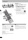
Do not connect the unit through a video
cassette recorder
Video signals fed through video cassette recorders will
be affected by copyright protection systems and the pic-
ture will not be shown correctly on the television.
Television
Video cable
(not included)
75 ≠ coaxial cable
(included) ➜below
Television
If the connector
doesn’t match
➜page 44
Red White Yellow
Connect last.
Also connect the AC
power supply cords for
the other equipment.
75 ≠ coaxial cable
≥The signal from the antenna passes through this unit and along
the 75 ≠ coaxial cable to the television even when this unit is
turned off. You don’t have to connect the antenna to the televi-
sion.
≥The picture and sound signal from this unit does not go through
the 75 ≠ coaxial cable to the television. Make sure you connect
one of the following terminals on this unit to the television: the
AUDIO/VIDEO terminal, the S-VIDEO OUT terminal or the COM-
PONENT VIDEO OUT terminal. If the television has none of
these terminals, consult your local dealer.
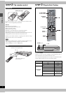
AC power supply cord (included)
Conserving power
This unit consumes a small amount of power, even when it is
turned off (approx. 3.2 W). To save power when the unit is not to
be used for a long time, unplug it from the household AC outlet.