


111
ClipLink Guide
Appendixes
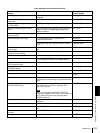
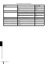
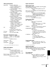
Example System Configuration and Operation Flow
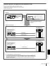
The following illustration shows an example system
configuration for using the ClipLink function and a typical
ClipLink operation flow.
Shooting
DVCAM camcorder
(DSR-130/130P/
300/300P/500WS/
500WSP)
DVCAM standard cassette or DVCAM mini cassette
Index pictures: recorded on
tape
ClipLink log data: recorded in
cassette memory
ClipLink log data recorded onto DVCAM
cassettes links shooting and editing
operations.
DSR-85/1800/1600
a)
or
DSR-85P/1800P/1600P
a)
Digital Videocassette
Recorder/Player
ClipLink log data transfer
Index pictures
Video output (SDTI)
b)
RS-422A interface
ES-7 EditStation non-
linear editing system
Editing
DSR-85
c)
/1800/1600
a)
or
DSR-85P
c)
/1800P/1600P
a)
Digital Videocassette
Recorder/Player
Actual AV data
SDTI input/output
b)
ES-7 EditStation non-
linear editing system
a) The DSR-1600/1600P is a videocassette player.
b) To transfer SDTI signals between the DSR-1800/1800P and ES-7, installation of the DSBK-1802
SDTI (QSDI) Input/Output Board on the DSR-1800/1800P is required; to send an SDTI signal from
the DSR-1600/1600P to the ES-7, installation of the DSBK-1602 SDTI (QSDI) Output Board on the
DSR-1600/1600P is required.
c) Between the DSR-85/85P and ES-7, quadruple transfer is possible through the SDTI interface.
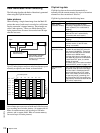
ClipLink log data