


90
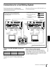
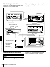
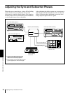
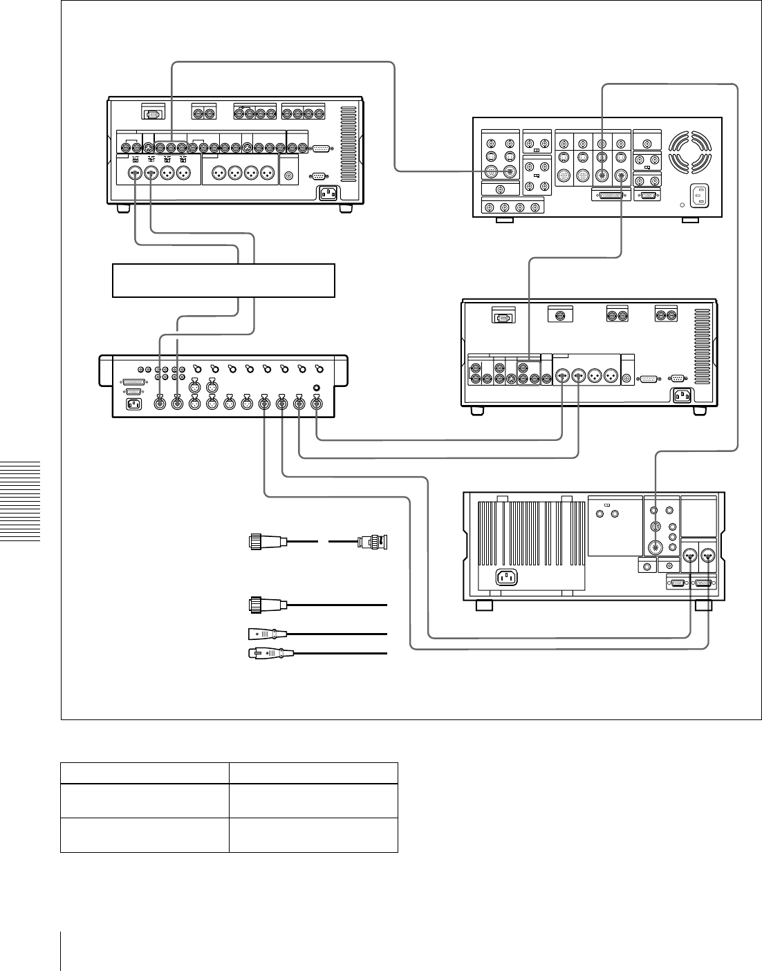
Connections for an A/B Roll Editing System
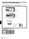
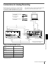
Chapter 5 Connections and Settings
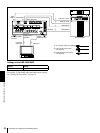
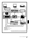
Video/audio signal connections
The following shows an example of video/audio signal
connections in an A/B roll editing system.
In this example, analog component signals are used as the
video signals and XLR 3-pin connectors are used as audio
input/output connectors.
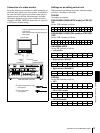
Settings on the DSR-1800/1800P (recorder) For details of the video/audio input and audio mode
settings, see “Settings for Recording” on page 31.
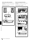
VIDEO INPUTS
COMPONENT 2
VIDEO INPUTS
COMPONENT 1
COMPONENT VIDEO OUT
Y, R–Y, B–Y
COMPONENT VIDEO IN
Y, R–Y, B–Y
PGM OUT
COMPONENT 1
AUDIO IN
CH-1
CH-2
LINE OUT 2 LINE OUT 1
1234MIC/LINE
IN
AUDIO OUT
CH-1 CH-2
COMPONENT 1
OUTPUT
AUDIO OUTPUT
CH-1
CH-2
CH-2 OUTCH-1 OUT
CH-2 INCH-1 IN
1
1
2
3
3
3
3
3
3
3
3
DFS-500/500P DME Switcher
C Cable with XLR
connectors (not supplied)
MXP-290
Audio Mixer
DSR-1800/1800P
(recorder)
UVW-1600/1600P (player 2)
A 12-pin/3-BNC cross cable
(not supplied; consult your
Sony dealer about this cable.)
DSR-1600/1600P
(player 1)
DPS-D7 or other delay unit
B 12-pin dubbing cable
(not supplied)
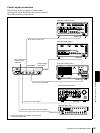
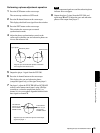
Switch/menu Setting
AUDIO IN LEVEL/600
Ω
switches
HIGH-ON
LEVEL SELECT menu item Normally +4 dBm
(see page
71)