


91
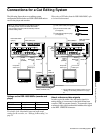
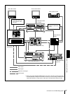
Connections for an A/B Roll Editing System
Chapter 5 Connections and Settings
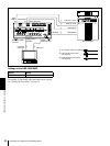
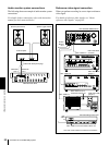
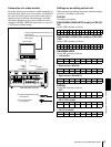
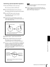
Connection of a video monitor
Set up the following connections to enable monitoring of
video and audio signals on a video monitor. In addition to
the video and audio signals, you can have time data, the
operation mode of the unit, alarm messages, and other
information displayed as text on the monitor screen by
setting the CHARA. DISPLAY menu item (see page 65)
to ON (factory default setting).
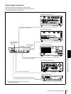
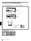
Settings on an editing control unit
When connecting an editing control unit, make the settings
as follows, according to the model.
PVE-500
No settings are required.
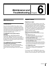
BVE-600/900/910/2000 (NTSC model) or FXE-100/
120
Set the VCR constants as follows.
BVE-600/900/910/2000 (PAL model) or FXE-100P/
120P
Set the VCR constants as follows.
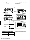
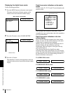
RM-450/RM-450CE
Set the DIP switches as follows.
• Left switches
• Right switches (RM-450)
)
• Right switches (RM-450CE)
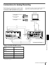
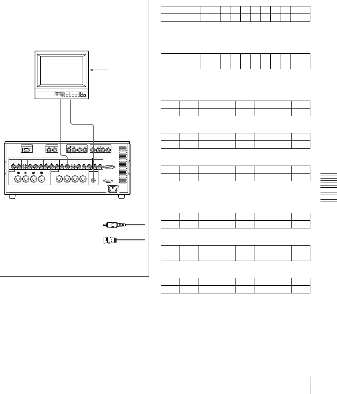
BVE-800
Set the DIP switches as follows.
•SW2
•SW3 (NTSC model)
•SW3 (PAL model)
VIDEO
OUT
2(SUPER)
AUDIO
MONITOR OUT
21
75 Ω termination switch: ON (or attach a 75
Ω terminator)
Input switches: Set according to the type of
input signals.
Video monitor
Audio input
Composite
video input
A Cable with RCA phono plugs
(not supplied)
B 75 Ω coaxial cable
(not supplied)
DSR-1800/1800P (recorder)
1 2 3 4 5 6 7 8 9 10 11 12 13 14 15
80 15 00 96 05 05 03 80 0A 08 FE 00 80 5A FF
1 2 3 4 5 6 7 8 9 10 11 12 13 14 15
81 15 00 7D 05 05 02 80 0A 07 FE 00 80 4C FF
76543210
OFF −−OFF −−−−
76543210
OFF − OFF ON OFF OFF ON ON
76543210
ON − OFF ON OFF OFF ON ON
12345678
ON OFF ON ON − ON ON −
12345678
ON ON ON OFF − ON OFF OFF
12345678
OFF OFF OFF ON − ON OFF OFF