


85
Connections for a Cut Editing System
Chapter 5 Connections and Settings
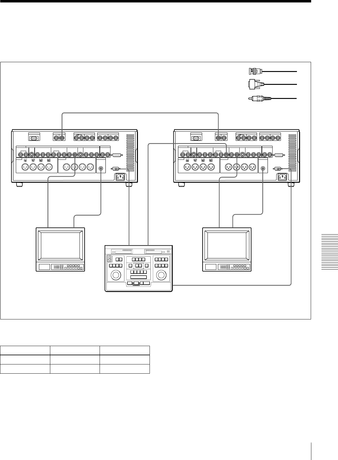
Connections for a Cut Editing System
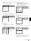
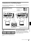
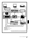
The following figure shows a cut editing system
configuration that includes two DSR-1800/1800P units to
serve as the player and recorder.
When using a VCR other than the DSR-1800/1800P, refer
to its instruction manual.
Settings on the DSR-1800/1800Ps (recorder and
player)
For details of the video/audio input and audio mode
settings for the recorder, see “Settings for Recording” on
page 31.
About reference video signals
In order to provide stable video and audio signals for
analog editing, it is necessary for the built-in time base
corrector (TBC) to operate correctly. To ensure this, input
a reference video signal synchronized with the video signal
to the REF. VIDEO IN connector.
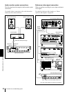
RECORDER
SDTI(QSDI)OUT
AUDIO
MONITOR
OUT
AUDIO
MONITOR
OUT
VIDEO
OUT 2
(SUPER)
REMOTE
SDTI(QSDI)IN
VIDEO
OUT 2
(SUPER)
REMOTE
REF.
VIDEO
OUT
REF.
VIDEO IN
PLAYER
1
1321 132
When you select assemble or insert editing mode on
the editing control unit, the two DSR-1800/1800P
units (recorder and player) will automatically enter the
selected editing mode.
A 75 Ω coaxial cable (not supplied)
C Cable with RCA phono plugs
(not supplied)
B 9-pin remote control cable
(not supplied)
DSR-1800/1800P
(player)
DSR-1800/1800P
(recorder)
Audio input
Composite
video input
Source monitor
Main monitor
Editing control unit (RM-450/
450CE, PVE-500, etc.)
a)
Audio input
a)
For the settings on the editing control unit, see
“Settings on an editing control unit” on page
91.
Composite
video input
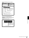
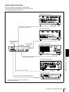
Button Recorder Player
REMOTE On (lit) On (lit)
9PIN On (lit) On (lit)