


24
Location and Function of Parts
Chapter 1 Overview
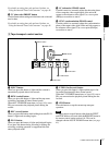
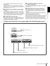
a DV IN/OUT connector (6-pin IEEE-1394)
(optional DSBK-1803 i.LINK/DV Input/Output
Board required)
This i.LINK-compatible connector (subsequently referred
to also as the i.DV IN/OUT connector) inputs and outputs
digital video and audio signals in DV format.
Note
When searching at speeds in the range +
1
/
2
to +
1
/
30
or
−
1
/
2
to −
1
/
30
times normal speed, the audio signal output
from this connector and monitored on external equipment
may sound differently from the audio signal played back
on this unit.
b SDTI (QSDI) (Serial Data Transport Interface
(QSDI)) IN/OUT connectors (BNC type) (optional
DSBK-1802 SDTI (QSDI) Input/Output Board
required)
The IN connector inputs and the OUT connector outputs
digital video and audio signals in SDTI (QSDI) format.
Note
When searching at speeds in the range +
1
/
2
to +
1
/
30
or
−
1
/
2
to −
1
/
30
times normal speed, the audio signal output
from this connector and monitored on external equipment
may sound differently from the audio signal played back
on this unit.
c SDI (Serial Digital Interface) IN (input) and active
through output connectors (BNC type) (optional
DSBK-1801 SDI/AES/EBU Input/Output Board
required)
Input digital video and audio signals in SDI format to the
left-hand connector. The right-hand connector is for an
active-through connection.
d SDI (Serial Digital Interface) OUT connectors
(BNC type) (optional DSBK-1801 SDI/AES/EBU
Input/Output Board required)
Output SDI-format digital video and audio signals. The
same signals are output from both connectors.
e DIGITAL AUDIO (AES/EBU) IN connectors
(BNC type) (optional DSBK-1801 SDI/AES/EBU
Input/Output Board required)
Input digital audio signals in AES/EBU format to these
connectors.
The left-hand connector (CH-1/2) is for audio channels 1
and 2, and the right-hand connector (CH-3/4) is for audio
channels 3 and 4.
f DIGITAL AUDIO (AES/EBU) OUT connectors
(BNC type) (optional DSBK-1801 SDI/AES/EBU
Input/Output Board required)
These connectors output digital audio signals in AES/EBU
format.
The left-hand connector (CH-1/2) is for audio channels 1
and 2, and the right-hand connector (CH-3/4) is for audio
channels 3 and 4.
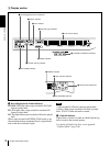
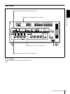
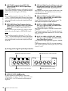
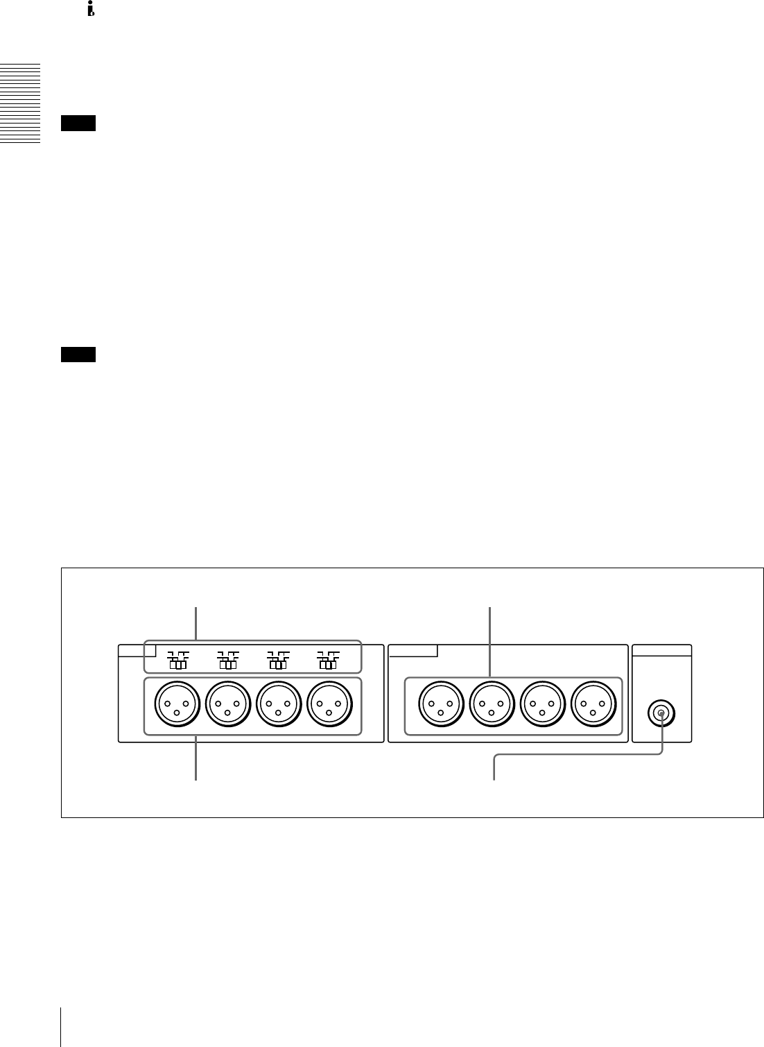
C Analog audio signal input/output section
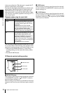
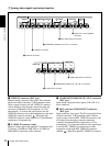
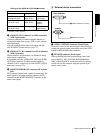
a AUDIO IN LEVEL/600 Ω
ΩΩ
Ω switches
Set these switches for each channel as shown in the
following table, according to the audio input levels to the
AUDIO IN CH-1 to CH-4 connectors and the required
impedance.
MONITOR OUT
AUDIO
LEVEL
AUDIO IN AUDIO OUT
CH-1
HIGH
LOW
OFF
CH-2 CH-3
CH-4
ON
600
Ω
LEVEL
HIGH
LOW
OFF
ON
600
Ω
LEVEL
HIGH
LOW
OFF
ON
600
Ω
LEVEL
HIGH
LOW
OFF
ON
600
Ω
CH-1
CH-2 CH-3
CH-4
d AUDIO MONITOR OUT connector
c AUDIO OUT CH-1 to CH-4 connectors
a AUDIO IN LEVEL/600 Ω switches
b AUDIO IN CH-1 to CH-4 connectors