


67
Menu Contents
Chapter 4 Menu Settings
VITC [> VITC]: Determine whether to record the internally
generated time code as VITC.
OFF [>> OFF]: Do not record the internally generated time
code as VITC. (VITC present in the input video signal is
recorded unchanged.)
*ON [>> ON]: Record the internally generated time code as
VITC.
TCG REGEN [>TCG regen]: Select the signal to be
regenerated when the time code generator is in the
regeneration mode (i.e., when the TC MODE menu item is
set to INT REGEN or EXT REGEN).
*TC & UB [>> TC & UB]: Both the time code and user bits are
regenerated.
TC [>> TC]: Only the time code is regenerated.
UB [>> UB]: Only the user bits are regenerated.
UB BINARY GP. [> Binary Gp.]: Select the user bit binary
group flag of the time code generator.
Note
When the TC MODE menu item is set to EXT REGEN, the
user-bit binary group flag setting follows the setting on the time
code input to this unit.
*000: NOT SPECIFIED [>> 000]: Character set not specified
001: ISO CHARACTER [>> 001]: 8-bit characters conforming
to ISO 646 and ISO 2022
010: UNASSIGNED-1 [>> 010]: Undefined
011: UNASSIGNED-2 [>> 011]: Undefined
100: UNASSIGNED-3 [>> 100]: Undefined
101: PAGE/LINE [>> 101]: Multiplex
110: UNASSIGNED-4 [>> 110]: Undefined
111: UNASSIGNED-5 [>> 111]: Undefined
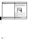
VITC POS SEL-1 [>VITC pos-1]: Select a line to insert the
VITC in.
Note
You can insert the VITC signal in two places. To insert it in two
places, set both this item and also VITC POS SEL-2.
(For DSR-1800)
12 LINE [>> 12 line] to 20 LINE [>> 20 line]: Select any line
from 12 to 20.
Factory default setting: 16 LINE [>> 16 line]
(For DSR-1800P)
Select a line to insert the VITC in.
9 LINE [>> 9 line] to 22 LINE [>> 22 line]: Select any line
from 9 to 22.
Factory default setting: 19 LINE [>> 19 line]
VITC POS SEL-2 [>VITC pos-2]: Select a line to insert the
VITC in.
Note
You can insert the VITC signal in two places. To insert it in two
places, set both this item and also VITC POS SEL-1.
(For DSR-1800)
12 LINE [>> 12 line] to 20 LINE [>> 20 line]: Select any line
from 12 to 20.
Factory default setting: 18 LINE [>> 18 line]
(For DSR-1800P)
Select a line to insert the VITC in.
9 LINE [>> 9 line] to 22 LINE [>> 22 line]: Select any line
from 9 to 22.
Factory default setting: 21 LINE [>> 21 line]
VITC OUTPUT [>VITC out]: Select the time code to be output
as VITC.
OFF [>> OFF]: Do not output VITC.
TC [>> TC]: Output TC after converting it into VITC.
*VITC [>> VITC]: Output VITC.
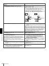
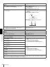
EE OUT PHASE [>EE out]: Determine the output phase for
the LTC signal output from the TIME CODE OUT
connector when recording time code and in STOP REC
mode (forced EE mode).
*MUTE [>>mute]: Mute the output.
THROUGH [>> through]: Output the time code input to the
TIME CODE IN connector as it is.
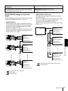
(See example
configuration on page 73
.
)
VIDEO INPUT PHASE [>> V input]: Output the time code
with the same phase as the input video signal phase.
(See example configuration on page 73.)
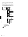
VIDEO OUTPUT PHASE [>> V output]: Output the time code
with the same phase as the output video signal phase.
(See example configuration on page 74.)
MUTE IN SRCH [>Mute in SR]: Select whether to mute the
output from the TIME CODE OUT connector in search
(jog/shuttle) mode.
OFF [>> OFF]: Do not mute.
*ON [>> ON]: Mute.
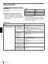
TIME CODE [Time code]: Settings related to the time code
generator
Description of settings