


117
Index
Index
Index
Numerics
9PIN button 20
A
A/B roll editing system 86
AC IN connector 21
Alarm messages 102
Analog audio signal input/output
section 24
Analog interfaces 10
Analog recording 93
Analog video signal input/output
section 22
Arrow buttons 16
Aspect ratio 11
AUDIO CH1 1/2 display 14
AUDIO CH2 3/4 display 14
AUDIO IN CH-1 to CH-4 connectors
25
AUDIO IN LEVEL/600-ohm switches
24
AUDIO INPUT LEVEL control knobs
14
Audio level meters 13
AUDIO MONITOR OUT connector
25
Audio monitor system connections 88
AUDIO OUT CH-1 to CH-4
connectors 25
Audio performance 107
AUTO FUNCTION execution menu
75
Auto mode execution menu 75
B
Basic items 59, 76
C
Cassette compartment 13
Cassette memory indicator 19
CH1,1/2 button 16
CH2,3/4 button 16
CHANNEL CONDITION indicators
19
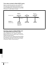
ClipLink 10
example system configuration
111
guide 110
index pictures 110, 112
log data 110, 112
ClipLink indicator 18
COMPONENT VIDEO IN Y/R-Y/B-
Y connectors 22
COMPONENT VIDEO OUT Y/R-Y/
B-Y connectors 23
Condensation 97
Connections 83
analog recording 93
audio monitor system 88
control signal 89
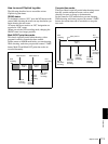
for A/B roll editing system 86
for cut editing system 85
for digital non-linear editing
system 83
for dubbing via i.LINK interface
56
for dubbing via SDTI (QSDI) 56,
92
video monitor 91
video/audio signals 90
CONTROL S connector 14
Control signal connections 89
COUNTER 49
COUNTER SEL button 16
Cue point 113
Cut editing system 85
D
DIGITAL AUDIO (AES/EBU) IN
connectors 24
DIGITAL AUDIO (AES/EBU) OUT
connectors 24
Digital dubbing 56
Digital hours meter 11, 97
display modes 97
indications in the time counter
display 98
indications on the monitor 98
Digital jog sound function 11
Digital signal input/output section 23
Digital slow-motion playback 11
Display section 18
Drop frame indication 48
DSBK-1801 SDI/AES/EBU Input/
Output Board 11
DSBK-1802 SDTI (QSDI) Input/
Output Board 11
DSBK-1803 i.LINK/DV Input/Output
Board 11
DVCAM 9
E
EBU 10
Editing control unit 91
EE OUT PHASE settings 73
THROUGH mode 73
VIDEO INPUT PHASE mode 73
VIDEO OUTPUT PHASE mode
74
EJECT button 17
Enhanced items 59, 78
Error messages 102
External device connectors 25
F
F FWD button 17
Factory default settings 79
FREE RUN 50
Front panel 13
H
Head cleaning 99
HEADPHONES connector 14
I
i.DV IN/OUT connector 24
i.LINK (DV) 10
i.LINK button 20
Index pictures 110, 112
Initial time code value 49
INPUT display 14
INPUT SELECT section 16
Input selection/audio mode display
section 14
Interfaces 10
Internal time code generator 49
FREE RUN 50
REC RUN 50
J
JOG indicator 19
Jog mode 20, 55
Jog sound function 11
L
Log data 110, 112
cue point 113
Mark IN/OUT points 113, 114
OK/NG status 113
recording capacity 114
M
Maintenance 97
condensation 97
head cleaning 99
regular checks 97
Mark IN/OUT points 113, 114
Menu 59
changing settings 76
contents 62
factory default settings 79