


13
Location and Function of Parts
Chapter 1 Overview
Location and Function of Parts
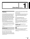
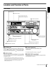
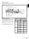
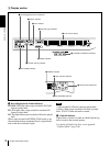
Front Panel
a POWER switch
Press the “” side to power the unit on. When the unit is
powered on, the display windows in the front panel lights.
To power the unit off, press the “” side of the switch.
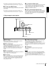
b Audio level meters
These show the audio levels of channels 1 to 4 (recording
levels in recording mode or E-E mode* and playback level
in playback mode).
* E-E mode: Abbreviation of “Electric-to-Electric mode.” In this mode,
video and audio signals input to the VCR are output after passing through
internal electric circuits, but not through magnetic conversion circuits such
as heads and tapes. This can be used to check input signals and for
adjusting input signal levels.
c Cassette compartment
Accepts DVCAM, DV and DVCPRO (25M)
videocassettes.
For details of usable cassettes, see page 27.
d PHONE LEVEL control knob
Controls the volume of the headphones connected to the
HEADPHONES connector.
INPUT
VIDEO
AUDIO
V:SDTI SDTI i.LINK
dB
0
-12
-20
-30
-40
-60
dB
0
1
0
-1
-2
OVER
1
dB
0
-12
-20
-30
-40
-60
dB
0
1
0
-1
-2
OVER
2
dB
0
-12
-20
-30
-40
-60
dB
0
1
0
-1
-2
OVER
3
dB
0
-12
-20
-30
-40
-60
dB
0
1
0
-1
-2
OVER
4
REC MODE
CH11/2
CH23/4
COMPOSITE
2CH4CHPB FS
Y-R,B
48k44.1k32k
S VIDEO
SDI SG
ANALOG
AES/EBU
SDI SG
ANALOG
AES/EBU
SDI SG
POWER
A B
MARK
A Input selection/audio mode
display section
(see page 14)
a POWER switch
c Cassette compartment
B Menu control panel (inside of
the door)
(see page 15)
F Remote control setting
section
(see page 20)
E Search control section
(see page 19)
D Display section
(see page 18)
g AUDIO INPUT LEVEL control knobs
e HEADPHONES connector
f CONTROL S connector
C Tape transport control section
(see page 17)
b Audio level meters
d PHONE LEVEL control knob