


46 Chapter 4 Menu Settings
Chapter 4 Menu Settings
Menu Contents
Menu contents (Continued)
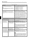
TAPE PROTECTION [Tape protect]: Settings related to
tape and video head protection
Description of settings
FROM STOP [> From
STOP]: Set the time to
switch from stop mode to
tape protection mode and
select the mode for
protecting the video
heads and video tape.
STOP TIMER [>> STP timer]:
Set the time to switch from
stop mode to tape protection
mode.
30 MIN [>>> 30 min] to 0.5 SEC [>>> 0.5 sec]: Select time
from 16 settings ranging from 0.5 seconds to 30 minutes in
steps of 0.1 second.
Factory default setting: 8MIN [>>> 8min]
NEXT MODE [>>> Next mode]:
Select tape protection mode
when time set in STOP
TIMER setting elapses.
∗STANDBY OFF [>>> STANDBY]: Standby off mode
TENSION RELEASE [>>> T.RLSE]: The tape tension is
released, but the picture can still be seen on the monitor.
Note
When the unit is in tension release mode, the head drum is
still rotating, so the picture can be output and monitored. That
is, it is still in “standby on” mode (i.e. is on standby).
Therefore, care should be taken over the setting if it is
critically important whether the unit is in “standby on” or
“standby off” mode (for example when the unit is used for
broadcasting).
FROM STILL [> From
STILL]: Set the time to
switch from still search
mode or playback pause
mode to tape protection
mode. Also select the
type of tape protection
mode to follow still search
mode when the set time
elapses (playback pause
mode is always followed
by tension release mode).
STILL TIMER [>> STL timer]:
Set the time to switch from
still search mode or
playback pause mode to
tape protection mode.
30 MIN [>>> 30 min] to 0.5 SEC [>>> 0.5 sec]: Select time
from 16 settings ranging from 0.5 seconds to 30 minutes in
steps of 0.1 second.
Factory default setting: 8MIN [>>> 8min]
NEXT MODE [>>> Next mode]:
Select the type of tape
protection mode to follow
still search mode when the
time set in “STILL TIMER”
elapses.
∗STEP FWD [>>> Step]: The tape is advanced at
1
/30 normal
speed for 2 seconds.
STANDBY OFF [>>> STANDBY]: Standby off mode
TENSION RELEASE [>>> T.RLSE]: The tape tension is
released, but the picture can still be seen on the monitor.
Note
When the unit is in step forward or tension release mode, the
head drum is still rotating, so the picture can be output and
monitored. That is, it is still in “standby on” mode (i.e. is on
standby). Therefore, care should be taken over the setting if
it is critically important whether the unit is in “standby on” or
“standby off” mode (for example when the unit is used for
broadcasting).
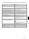
TIME CODE [Time code]: Settings related to the time
code generator
Description of settings
UB BINARY GP. [> UB Binary Gp]: Select the user bit
binary group flag of the time code generator
Note
When the TC MODE menu item is set to EXT REGEN, the
user-bit binary group flag setting follows the setting on the
time code input to this unit.
∗000: NOT SPECIFIED [>> 000]: Character set not specified
001: ISO CHARACTER [>> 001]: 8-bit characters
conforming to ISO 646 and ISO 2022
010: UNASSIGNED-1 [>> 010]: Undefined
011: UNASSIGNED-2 [>> 011]: Undefined
100: UNASSIGNED-3 [>> 100]: Undefined
101: PAGE/LINE [>> 101]: Mutliplex
110: UNASSIGNED-4 [>> 110]: Undefined
111: UNASSIGNED-5 [>> 111]: Undefined
TC EE OUT MODE [> TC out mod]: This only appears when
the optional DSBK-130/130P Timecode Input/Output
Board is installed.
It controls the phase of the LTC signal output when
recording timecode and in “STOP REC” mode (forced EE
mode).
∗MUTE [>> mute]: Output no timecode.
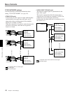
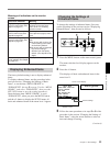
THROUGH [>> through]: Output LTC with the phase
synchronized to the signal input to the TIME CODE IN
connector. Use this mode when the signal input to the
VIDEO IN connectors is not synchronized to the reference
video signal. (See the example configuration on page 48.)
VIDEO INPUT PHASE [>> V input]: Output LTC with the phase
synchronized to the input video signal. Use this mode when
using the video input in a bridging (loop-through)
connection. (See the example configuration on page 48.)
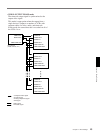
VIDEO OUTPUT PHASE [>> V output]: Output LTC with the
phase synchronized to the output video signal. Use this
mode when using a bridging (loop-through) connection from
the output video to the input video. (See the example
configuration on page 49.)