


62 Chapter 5 Connections and Settings
Chapter 5 Connections and Settings
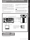
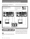
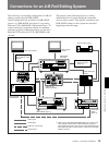
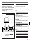
Connections for an A/B Roll Editing System
Video/audio signal connections
The following shows an example of video/audio signal
connections in an A/B roll editing system. In this
example, analog component signals are used as the
video signals and XLR 3-pin connectors are used as
audio input/output connectors.
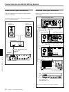
Settings on the DSR-85/85P (recorder)
For details of the video/audio input and audio mode
settings, see “Settings for Recording” (page 19).
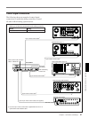
DFS-500/500P
DME Switcher
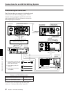
Switch Setting
AUDIO IN 600 Ω ON/OFF ON
AUDIO IN –6dBm/0dBm/+4dBm Normally +4dBm
1 12-pin/3-BNC cross cable (not
supplied) (Consult your Sony
dealer about this cable.)
2 12-pin dubbing cable (not
supplied)
3 Cable with XLR connectors
(not supplied)
UVW-1600/1600P (player 2)
DSR-60/60P (player 1)
MXP-290
Audio Mixer
DSR-85/85P
(recorder)
DPS-D7 or other delay unit
VIDEO INPUTS
COMPONENT 2
VIDEO INPUTS
COMPONENT 1
COMPONENT VIDEO
Y, R–Y, B–Y/RGB OUT
COMPONENT VIDEO IN
(Y, R–Y, B–Y)
PGM OUT
COMPONENT 1
AUDIO IN
CH-1
CH-2
LINE OUT 2 LINE OUT 1
1234MIC/LINE IN
AUDIO OUT
CH-1 CH-2
COMPONENT 1
OUTPUT
AUDIO OUTPUT
CH-1
CH-2
1
3
3
1
2
3
3
3
3
CH-2 OUTCH-1 OUT
CH-2 IN
CH-1 IN
3
3
REMOTE
AC IN
ANALOG I/O
REF.VIDEO VIDEO OUT
MONITOR
AUDIO
S VIDEO OUT
AUDIO OUT
QSDI
COMPONENT VIDEO
TBC REMOTE
SDI OUTPUT
TIME CODE OUT