


Chapter 5 Connections and Settings 61
Chapter 5 Connections and Settings
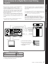
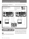
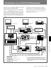
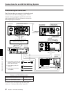
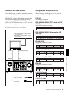
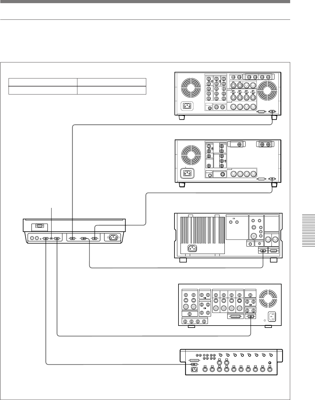
Control signal connections
The following shows an example of control signal
connections to enable the editing controller to control
all other A/B roll editing system devices.
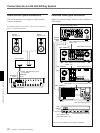
9-pin remote control cable
a)
UVW-1600/1600P (player 2)
9-pin remote control cable
a)
Mixer control mode selection
switch: PARALLEL
DSR-60/60P (player 1)
DFS-500/500P DME Switcher
9-pin remote control cable
a)
DSR-85/85P (recorder)
EDITOR (15-pin)
MXP-290 Audio Mixer
9-pin remote control cable
a)
9-pin/15-pin mixer control cable (not supplied)
a) Use the 9-pin remote control cable supplied with this unit or an
optional RCC-5G/10G/30G cable.
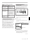
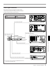
Setting on all devices controlled from the editing controller
Switch Setting
REMOTE/LOCAL REMOTE
PVE-500 Editing
Control Unit
SWITCHER PLAYER 2MIXER
PLAYER 1
RECORDER
REMOTE
REMOTE
REMOTE
EDITOR
REMOTE
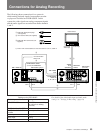
AC IN
ANALOG I/O
REF.VIDEO VIDEO OUT
MONITOR
AUDIO
S VIDEO OUT
AUDIO OUT
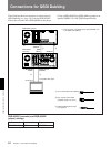
QSDI
COMPONENT VIDEO
TBC REMOTE
SDI OUTPUT
TIME CODE OUT