


– 30 –
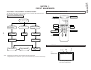
KL-W7000/W9000
RM-Y980
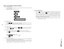
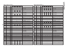
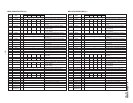
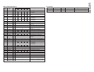
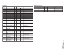
Adjustment Items and Procedure Tools and Test Points Adjustment Places Illustration Waveforms and Values
Signals
* L5002
* L5004
* 13.67±0.10MHz
*
* 10.22±0.05MHz
*
* NTSC signal
* Frequency counter
* Double speed NTSC
* Oscilloscope
* NTSC signal
* Frequency counter
* Double speed NTSC
* Oscilloscope
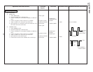
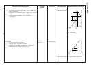
C Board Adjustment
1. PLL fo adjustment
1) WIDE mode
1. Select WIDE mode.
2. Open the CN5202 pin 1, H.SYNC input.
3. Connect *IC5004 pin 2 to the GND (*TP5009) via 100Ω resis-
tance.
4. Connect *frequency counter to the pin 1 of *IC5004.
5. Adjust *L5002 so as to satisfy the *specified value.
6. Input H.SYNC for NT double speed, and confirm the wave-
form at the *TP with *oscilloscope.
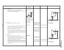
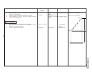
2) NORMAL mode
1. Select NORMAL mode.
2. Open the CN5202 pin 1, H.SYNC input.
3. Connect *IC5004 pin 2 to the GND (*TP5009) via 100Ω resis-
tance.
4. Connect *frequency counter to the pin 1 of *IC5004.
5. Adjust *L5004 so as to satisfy the *specified value.
6. Input H.SYNC for NT double speed
7. Confirm the waveform at the *TP5004 with *oscilloscope.
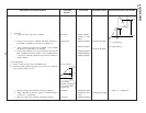
* IC5004 pin 2
* TP5009 Jig land
* IC5004
* TP5007 (RPD2)
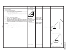
* IC5004 pin 2
* IC5009
* IC5004 pin 1
* TP5007 (RPD1)
31.78µs
2.39±0.1µs
5.0Vp-p
Use TP5009 as
reference GND.
Use TP5009 as
reference GND.
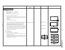
2.3±0.3 V