


– 32 –
KL-W7000/W9000
RM-Y980
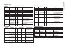
Adjustment Items and Procedure Tools and Test Points Adjustment Places Illustration Waveforms and Values
Signals
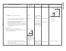
* TP5611 [BLBS]
* TP5607 is Ref.
GND
* TP5603 [B-SIG2]
* TP5603 [B-SIG2]
* TP 5602 [B-SIG1]
* TP5604 [B-SIG3]
* TP5603 [B-SIG2]
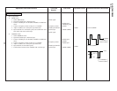
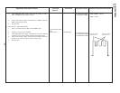
3) B channel
1. Using *DC power, apply 0V to *TP5611.
2. Connect *oscilloscope to *TP5603, and adjust *RV5605 so
that 10 IRE ~ 100 IRE (A) becomes *1.35±0.02Vp-p.
3. Adjust *RV5601 so that the forward 10 IRE ~ reverse 10 IRE
(B) becomes *5.90±0.02Vp-p at *TP5603.
4. Confirm that a difference in voltage amplitude of forward 10
IRE ~ 100 IRE and forward 10 IRE ~ reverse 10 IRE between
waveform at *TP5602,*TP5604 and waveform at *TP5603 is
within ±150mV.
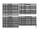
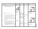
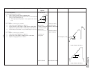
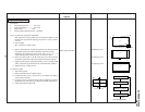
4. Vcom Adjustment
• *Using *I
2
C bus encoder, set the NT-WIDE mode.
• *Enter NT double speed 10-step signal of *bias 2.2V and amplitude
1.8Vp-p to the CN5201 pins 2~4.
*I
2
C bus encoder
*
* DC power
* Oscilloscope
* RV5605 [B. GAIN]
* RV5601 [B. BIAS]
* A : 1.35±0.02Vp-p
* B : 5.90±0.02Vp-p
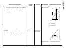
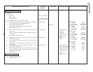
* TP5203 [Rch OUT]
* TP5205 [R-Vcom
OUT]
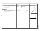
* TP5403 [Gch OUT]
* (Value in 1) – 0.60±0.02V
* RV5202 [R.VCOM]
1. Measure voltage at the *TP5203 with digital voltmeter.
2. Adjust *RV5202 so that the voltage at *TP5205 becomes
*(Value in 1) – 0.60±0.02V.
3. Measure voltage at the *TP5403 with digital voltmeter.
* Voltmeter
* Voltmeter
Use TP5201,
TP5401 and TP5601
as reference GND
respectively.
10
GND
IRE
100 IRE
$
4
2.0 ± 0.02 Vp-p
2.7 ± 0.02 V
10
A
B
100 IRE
IRE
10 IRE