


22
INTERNAL REGISTERS
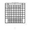
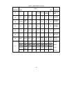
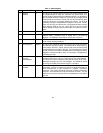
The COM20020 contains eight internal registers.
Tables 2 and 3 illustrate the COM20020
register map. Reserved locations should not be
accessed. All undefined bits are read as
undefined and must be written as logic "0".
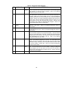
Interrupt Mask Register (IMR)
The COM20020 is capable of generating an
interrupt signal when certain status bits become
true. A write to the IMR specifies which status
bits will be enabled to generate an interrupt. The
bit positions in the IMR are in the same position
as their corresponding status bits in the Status
Register and Diagnostic Status Register. A logic
"1" in a particular position enables the
corresponding interrupt. The Status bits capable
of generating an interrupt include the Receiver
Inhibited bit, New Next ID bit, Excessive NAK
bit, Reconfiguration Timer bit, and Transmitter
Available bit. No other Status or Diagnostic
Status bits can generate an interrupt.
The five maskable status bits are ANDed with
their respective mask bits, and the results are
ORed to produce the interrupt signal. An RI
or TA interrupt is masked when the
corresponding mask bit is reset to logic "0", but
will reappear when the corresponding mask bit
is set to logic "1" again, unless the interrupt
status condition has been cleared by this time.
A RECON interrupt is cleared when the "Clear
Flags" command is issued. An EXCNAK
interrupt is cleared when the "POR Clear Flags"
command is issued. A New Next ID interrupt is
cleared by reading the Next ID Register. The
Interrupt Mask Register defaults to the value
0000 0000 upon hardware reset.
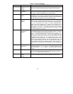
Data Register
This read/write 8-bit register is used as the
channel through which the data to and from the
RAM passes. The data is placed in or retrieved
from the address location presently specified by
the address pointer. The contents of the Data
Register are undefined upon hardware reset. In
case of READ operation, the Data Register is
loaded with the contents of COM20020 Internal
Memory upon writing Address Pointer low only
once.
Tentative ID Register
The Tentative ID Register is a read/write 8-bit
register accessed when the Sub Address Bits
are set up accordingly (please refer to the
Configuration Register). The Tentative ID
Register can be used while the node is on-line
to build a network map of those nodes existing
on the network. It minimizes the need for
operator interaction with the network. The node
determines the existence of other nodes by
placing a Node ID value in the Tentative ID
Register and waiting to see if the Tentative ID
bit of the Diagnostic Status Register gets set.
The network map developed by this method is
only valid for a short period of time, since nodes
may join or depart from the network at any time.
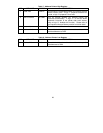
When using the Tentative ID feature, a node
cannot detect the existence of the next logical
node to which it passes the token. The Next ID
Register will hold the ID value of that node. The
Tentative ID Register defaults to the value 0000
0000 upon hardware reset only.
Node ID Register
The Node ID Register is a read/write 8-bit
register accessed when the Sub Address Bits
are set up accordingly (please refer to the
Configuration Register). The Node ID Register
contains the unique value which identifies this
particular node. Each node on the network
must have a unique Node ID value at all times.
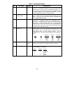
The Duplicate ID bit of the Diagnostic Status
Register helps the user find a unique Node ID.
Refer to the Initialization Sequence section for
further detail on the use of the DUPID bit. The
core of the COM20020 does not wake up until a
Node ID other than zero is written into the Node
ID Register. During this time, no microcode is
executed, no tokens are passed by this node,
and no reconfigurations are caused by this
node. Once a non-zero NodeID is placed into
the Node ID Register, the core wakes up but will
not join the network until the TXEN bit of the
Configuration Register is set. While the