


36
The third possibility which may occur after a
FREE BUFFER ENQUIRY is issued is if the
destination node does not respond at all. In this
case, the TA bit is set to a logic "1", while the
TMA bit remains at a logic "0". The user should
determine whether the node should try to
reissue the transmit command.
The fourth possibility is if a non-traditional
response is received (some pattern other than
ACK or NAK, such as noise). In this case, the
token is not passed onto the next node, which
causes the Lost Token Timer of the next node to
time out, thus generating a network
reconfiguration.
The "Disable Transmitter" command may be
used to cancel any pending transmit command
when the COM20020 next receives the token.
Normally, in an active network, this command
will set the TA status bit to a logic "1" when the
token is received. If the "Disable Transmitter"
command does not cause the TA bit to be set in
the time it takes the token to make a round trip
through the network, one of three situations
exists. Either the node is disconnected from the
network, or there are no other nodes on the
network, or the external receive circuitry has
failed. These situations can be determined by
either using the improved diagnostic features of
the COM20020 or using another software
timeout which is greater than the worst case
time for a round trip token pass, which occurs
when all nodes transmit a maximum length
message.
Receive Sequence
A receive sequence begins with the RI status bit
becoming a logic "1", which indicates that a
previous reception has concluded. The
microcontroller will be interrupted if the
corresponding bit in the Interrupt Mask Register
is set to logic "1". Otherwise, the
microcontroller must periodically check the
Status Register. Once the microcontroller is
alerted to the fact that the previous reception
has concluded, it may issue the "Enable
Receive to Page fnn" command, which resets
the RI bit to logic "0" and selects a new page in
the RAM buffer. Again, the appropriate buffer
size is specified in the "Define Configuration"
command. Typically, the page which just
received the data packet will be read by the
microcontroller at this point. Once the "Enable
Receive to Page fnn" command is issued, the
microcontroller attends to other duties. There is
no way of knowing how long the new reception
will take, since another node may transmit a
packet at any time. When another node does
transmit a packet to this node, and if the
"Define Configuration" command has enabled
the reception of long packets, the COM20020
interprets the packet as either a long or short
packet, depending on whether the content of the
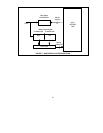
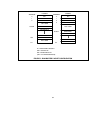
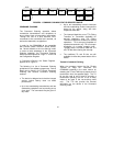
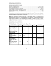
buffer location 2 is zero or non-zero. The format
of the buffer is shown in Figure 8. Address 0
contains the Source Identifier (SID), Address 1
contains the Destination Identifier (DID), and
Address 2 contains, for short packets, the value
256-N, where N represents the message length,
or for long packets, the value 0, indicating that it
is indeed a long packet. In the latter case,
Address 3 contains the value 512-N, where N
represents the message length. Note that on
reception, the COM20020 deposits packets into
the RAM buffer in the same format that the
transmitting node arranges them, which allows
for a message to be received and then
retransmitted without rearranging any bytes in
the RAM buffer other than the SID and DID.
Once the packet is received and stored correctly
in the selected buffer, the COM20020 sets the
RI bit to logic "1" to signal the microcontroller
that the reception is complete.