


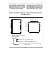

5
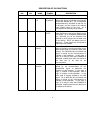
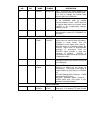
DIP PIN
NO.
PLCC PIN
NO.
NAME
SYMBOL DESCRIPTION
19 23 nReset in nRESET IN Input. This active low signal issued by the
microcontroller executes a hardware reset.
It is used to activate the internal reset
circuitry within the COM20020.
20 24 nInterrupt nINTR Output. This active low signal is generated
by the COM20020 when an enabled
interrupt condition occurs. nINTR returns to
its inactive state when the interrupt status
condition or the corresponding interrupt
mask bit is reset.
21 25 nChip Select nCS Input. This active low signal issued by the
microcontroller selects the COM20020 for
an access.
TRANSMISSION MEDIA INTERFACE
16,15 19,18 nPulse 2,
nPulse 1
nPULSE2,
nPULSE1
Output. In Normal Mode, these active low
signals carry the transmit data information,
encoded in pulse format, from the
COM20020 to the media driver circuitry.
When the device is in Backplane Mode, the
nPULSE1 signal driver is programmable
(push/pull or open-drain), while the
nPULSE2 signal provides a clock with
frequency of crystal/4. nPULSE1 is
connected to a weak internal pull-up resistor
in backplane mode.
17 20 Receive In RXIN Input. This signal carries the receive data
information from the line receiver circuitry to
the COM20020.
18 21 nTransmit
nEnable
nTXEN
Output. This signal is used prior to the
Power-up to enable the line drivers for
transmission. The polarity of the signal is
programmable by grounding the nPULSE2
pin.
nPULSE2 floating before Power-up: nTXEN
active low (Default option)
nPULSE2 grounded before Power-up:
nTXEN active high (This option is only
available in Backplane Mode)
MISCELLANEOUS
13,14 16,17 Crystal
Oscillator
XTAL1,
XTAL2
An external crystal should be connected to
these pins. If an external TTL clock is used