


35
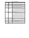
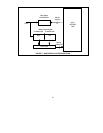
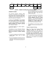
buffer address 2 contains a zero or non-zero
value. The format of the buffer is shown in
Figure 8. Address 0 contains the Source
Identifier (SID); Address 1 contains the
Destination Identifier (DID); Address 2 (COUNT)
contains, for short packets, the value 256-N,
where N represents the number of information
bytes in the message, or for long packets, the
value 0, indicating that it is indeed a long
packet. In the latter case, Address 3 (COUNT)
would contain the value 512-N, where N
represents the number of information bytes in
the message. The SID in Address 0 is used by
the receiving node to reply to the transmitting
node. The COM20020 puts the local ID in this
location, therefore it is not necessary to write
into this location.
Please note that a short packet may contain
between 1 and 253 data bytes, while a long
packet may contain between 257 and 508 data
bytes. A minimum value of 257 exists on a long
packet so that the COUNT is expressable in
eight bits. This leaves three exception packet
lengths which do not fit into either a short or
long packet; packet lengths of 254, 255, or 256
bytes. If packets of these lengths must be sent,
the user must add dummy bytes to the packet
in order to make the packet fit into a long
packet.
Once the packet is written into the buffer, the
microcontroller awaits a logic "1" on the TA bit,
indicating that a previous transmit command
has concluded and another may be issued.
Each time the message is loaded and a transmit
command issued, it will take a variable amount
of time before the message is transmitted,
depending on the traffic on the network and the
location of the token at the time the transmit
command was issued. The conclusion of the
Transmit Command will generate an interrupt if
the Interrupt Mask allows it. If the device is
configured for the Command Chaining
operation, please see the Command Chaining
section for further detail on the transmit
sequence. Once the TA bit becomes a logic "1",
the microcontroller may issue the "Enable
Transmit from Page fnn" command, which
resets the TA and TMA bits to logic "0". If the
message is not a BROADCAST, the COM20020
automatically sends a FREE BUFFER
ENQUIRY to the destination node in order to
send the message. At this point, one of four
possibilities may occur.
The first possibility is if a free buffer is available
at the destination node, in which case it
responds with an ACKnowledgement. At this
point, the COM20020 fetches the data from the
Transmit Buffer and performs the transmit
sequence. If a successful transmit sequence is
completed, the TMA bit and the TA bit are set to
logic "1". If the packet was not transmitted
successfully, TMA will not be set. A successful
transmission occurs when the receiving node
responds to the packet with an ACK. An
unsuccessful transmission occurs when the
receiving node does not respond to the packet.
The second possibility is if the destination node
responds to the Free Buffer Enquiry with a
Negative AcKnowledgement. A NAK occurs
when the RI bit of the destination node is a logic
"1". In this case, the token is passed on from
the transmitting node to the next node. The next
time the transmitter receives the token, it will
again transmit a FREE BUFFER ENQUIRY. If a
NAK is again received, the token is again
passed onto the next node. The Excessive NAK
bit of the Diagnostic Status Register is used to
prevent an endless sending of FBE's and NAK's.
If no limit of FBE-NAK sequences existed, the
transmitting node would continue issuing a Free
Buffer Enquiry, even though it would
continuously receive a NAK as a response. The
EXCNAK bit generates an interrupt (if enabled)
in order to tell the microcontroller to disable the
transmitter via the "Disable Transmitter"
command. This causes the transmission to be
abandoned and the TA bit to be set to a logic "1"
when the node next receives the token, while the
TMA bit remains at a logic "0". Please refer to
the Improved Diagnostics section for further
detail on the EXCNAK bit.