


Performance Check and Calibration Procedures
1–6
TPG20 Service
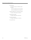
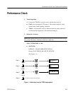
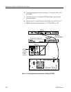
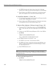
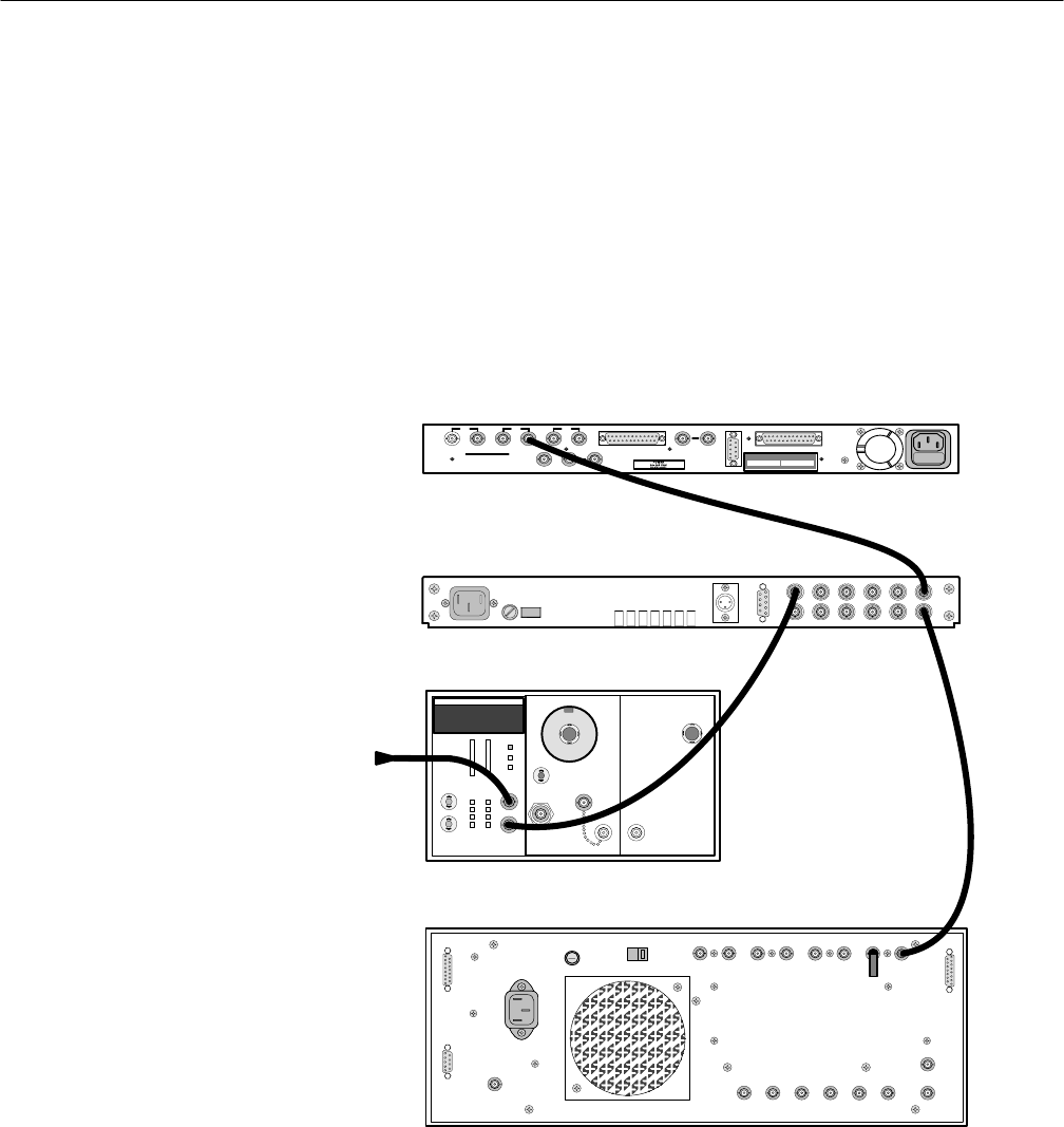
b. Connect the equipment as shown in Figure 1–2, using the TSG–170A
and 1780R.
c. Verify the presence of a standard NTSC Black Burst signal with the
waveform monitor.
d. Set the frequency counter Function to Ratio B/A, and AVG set to 10
7
.
e. Check – that the measured frequency is 3.579545 MHz ± 2 Hz.
SUBCARRIER
OUTPUT
75W
GENLOCK
LOOP–THROUGH
C
B
OUTPUTS C B A
R – B – G
Pr –Pb– Y
C–COMP–Y
A
LINE TRIGGER
SERIAL
DIGITAL
OUTPUTS
PARALLEL DIGITAL OUTPUT
REFERENCE
INPUT
RS232
PARALLEL DATA LOAD INPUT
SNELL & WILCOX Ltd.
SERIAL No.
MODEL No.
MADE IN ENGLAND
TSG-170A / TSG-271
TPG20
1780R / 1781R
DC5009
RF OUT
2nd LO IN
1st LO IN
AUX RF
OUT
TM5003
WWV
or other
precision,
1 MHz
reference
CH A
Figure 1–2: Initial equipment connections for checking the TPG20