Performance Check and Calibration Procedures
1–16
TPG20 Service
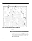
d. Connect the RF Input cable to the RF Output on the RF Bridge.
e. Select Demod/tracking generator on the spectrum analyzer and turn on
the analyzer Tracking Generator.
f. Set the spectrum analyzer tracking generator Fixed Level to 0.00 dBm.
g. Set the spectrum analyzer Span/Div to 1 MHz and the resolution
bandwidth to 3 kHz.
h. Set the vertical scale to 10 dB.
i. Set the Reference Level to the first major division from the top on the
spectrum analyzer.
j. Remove one of the cables from the RF Bridge.
k. Set the spectrum analyzer cursor to 5 MHz and then set the marker to 5
MHz.
l. Reconnect the cable removed in part j to the RF Bridge.
m. Note the Reference Level Readout.
n. Adjust the spectrum analyzer External Attenuation Amplitude by the
amount noted in part m. Note: The Reference Level Readout should
now be 0.00 dBm.
o. Connect the precision high frequency 75 W terminator to the Device
Under Test connector on the RF Bridge.
p. Check – that the frequency response from 0 MHz to 4.5 MHz is v40
dBm.
q. Return the frequency marker to 5 MHz if it was moved.
r. Remove the precision high frequency terminator from the RF Bridge.
s. Connect the Device Under Test connector on the RF Bridge to the
Reference Input on the TPG20 through a male–to–male bnc adapter.
Terminate the TPG20 Reference Input loop through with the precision
high frequency terminator used in part o.
t. Check – for a Reference Level Readout on the spectrum analyzer of
w36 dBm up to 4.5 MHz.
u. Move the RF Bridge to each of the 6 TPG20 Analog Outputs in turn,
checking for a Reference Level Readout on the spectrum analyzer of
w36 dBm.


