


Performance Check and Calibration Procedures
TPG20 Service
1–7
PAL 4.43361875 MHz ±1 Hz
f. Set TPG20:
FORMAT – 625/50 COMPOSITE PAL/D2
Groups; FLAT FIELDS; BLACK 625 PAL/D2
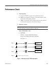
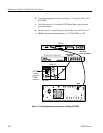
g. Connect the equipment as shown in Figure 1–2, using the TSG–271 and
1781R.
h. Connect frequency counter (referenced to WWV) set to ratio B/A to
TSG-271 Sub Carrier Output.
i. Check – that the measured frequency is 4.43361875 MHz ± 1 Hz.
3. Amplitude Accuracy < ± 1.0% All Analog Output Modes
a. Set TPG20:
FORMAT 625/50 COMPONENT RGB
Groups: LINEARITY; RAMP 100% 625 RGB
b. Use VM700A to check amplitude accuracy of 1.0 V ±1.0% p-p, using
the level meter mode (measure position view). Check levels out of all six
TPG20 Analog Outputs (both A Outputs, both B Outputs, and both C
Outputs).
c. Set TPG20:
FORMAT 525/60 COMPONENT RGB
Groups; LINEARITY; RAMP 100% 525 RGB
d. Use VM700A to check amplitude accuracy of 1.0 V ±1% p-p, using
level meter mode.
Check levels out of all six TPG20 Analog Outputs (both A Outputs, both
B Outputs, and both C Outputs).
e. Set TPG20:
FORMAT 525/60 COMPOSITE NTSC D2
Groups: LINEARITY; RAMP 100% 525 NTSC
f. Use VM700A to check for a composite video signal of 1.0V ±1.0%
(peak to peak measurement) on both of the TPG20 B Analog Outputs.
g. Set TPG20:
FORMAT 625/50 COMPOSITE PAL/D2