


Performance Check and Calibration Procedures
1–12
TPG20 Service
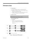
e. Set TPG20 Genlock to On. Select Lock on: Sync Lock. Verify that
genlock occurs within 20 seconds and Genlock light is on (not blinking).
f. Select H–phase on the TPG20 and rotate knob to verify that horizontal
phase can be adjusted at least ±one half line. Return setting to 0 nS.
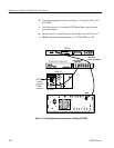
12. Vertical Phase Adjustment – 1 Frame – PAL
a. Use same test set–up as step 11 except trigger the oscilloscope externally
from the TPG20 TRIGGER OUT connector.
b. Select V–phase on the TPG20 and rotate knob. Verify that vertical phase
can be adjusted at least one frame. Return setting to line 1.
13. Subcarrier Phase Adjustment – 360 degrees in steps of 1 degree – PAL
a. Connect the TSG–271 Black Burst signal to the TPG20 REFERENCE
Input. Connect the other side of the loopthrough to the VM700A CH B
input.
b. Connect one of the TPG20 Analog B Outputs to CH A of the VM700A.
c. Set TPG20:
FORMAT 625/50 COMPOSITE PAL/D2
Groups: BARS; EBU COLOR BARS 625 PAL/D2
d. Set TPG20 to Genlock. Lock ON; SC – lock
e. Set VM700 to vector mode – burst reference to CH B.
f. Set TPG20 to SC–phase, rotate knob and observe that VM700A vector
display is capable of being adjusted over the full 360 degrees. Return
SC –phase adjustment to 0.
g. Switch TPG20 Genlock to off.
NOTE. The only requirement for steps 14 through 19 is to make sure that the
selected signal is the one actually output. Verification of signal specifications is
not needed at this time.
14. Check Serial Digital Outputs PAL D2
a. Set TPG20:
FORMAT 625/50 COMPOSITE PAL/D2